Hummer H1 (2002+). Manual — part 165
_____________________________________________________________________
Body 10-31
®
05745159
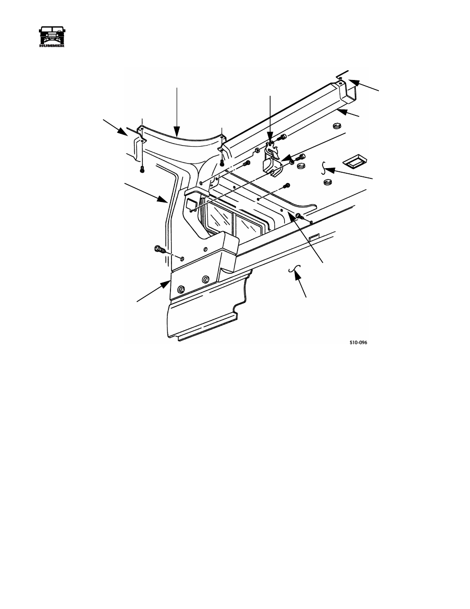
Figure 10-49: Station Wagon Side Wall Component Breakdown
B-PILLAR TRIM
C-PILLAR
CENTER TRIM
SEAT BELT BRACKET
HEADLINER
SEAT BELT ASSEMBLY
STATION WAGON
COMPARTMENT SIDE WALLS
TRIM PANEL
LOWER REAR
COMPARTMENT
WALL
UPPER C-PILLAR TRIM
LOWER C-PILLAR TRIM
10-32
Body
______________________________________________________________________
®
Inner Kick Panels Replacement
Removal
1.
Remove seats.
NOTE:
Remove one bolt, washer, and seat buckle for two-pas-
senger models.
2.
Remove bolts, washers, and seat buckles from front and
rear of tunnel (Figure 10-50).
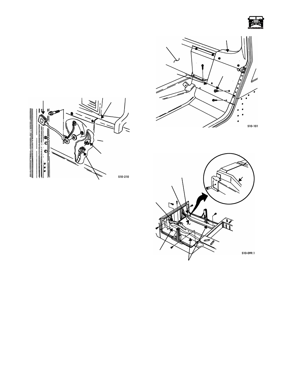
Figure 10-50: Seat Belt Buckle Electrical
Connector Location
NOTE:
Ensure seat belt buckle electrical connector or wiring
harness is pulled out and away from kick panel for ease of in-
stallation.
3.
Disconnect seat belt buckle electrical connector from
wiring harness connector on driver side.
NOTE:
Perform steps 4 and 5 for four-passenger models only.
4.
Remove panel fasteners, screw/washer assemblies, and
rear wall trim from rear compartment wall (Figure 10-51).
5.
Remove panel fasteners and rear inner kick panel from
tunnel (Figure 10-52).
Figure 10-51: Rear Compartment Trim Removal
Figure 10-52: Inner Kick Panel Mounting
6.
Remove front and center consoles.
7.
Remove screw/washer assemblies, panel fastener, and
shift control panel from tunnel (Figure 10-52).
8.
Remove panel fasteners and left front inner kick panel
from tunnel.
9.
Remove panel fasteners and right front inner kick panel.
NOTE:
Perform step 10 for two-passenger models only.
10. Remove panel fastener and inner kick panel from rear of
tunnel.
SEAT BUCKLE
SEAT BELT BUCKLE
ELECTRICAL
CONNECTOR
B-BEAM
WIRING
HARNESS
CONNECTOR
TRIM
REAR
REAR
PANEL
FASTENER
WALL TRIM
COMPARTMENT
COMPARTMENT
WALL
PANEL
RIGHT FRONT
TUNNEL
LEFT FRONT
REAR INNER
TWO PASSENGER
VEHICLE ONLY
KICK PANELS
INNER KICK
PANEL
INNER KICK PANEL
SHIFT
CONTROL
TRIM PANEL
KICK
PANEL

_____________________________________________________________________
Body 10-33
®
05745159
Installation
NOTE:
Perform step 1 for two-passenger models only.
1.
Secure rear inner kick panel to right rear of tunnel with
panel fastener (Figure 10-52).
2.
Secure right front inner kick panel to tunnel with panel
fasteners.
3.
Secure left front inner kick panel to tunnel with panel
fasteners.
4.
Secure shift control trim panel to tunnel with screw/
washer assemblies and panel fastener.
5.
Install center and front consoles.
NOTE:
Perform steps 6 and 7 for four-passenger models only.
6.
Secure rear inner kick panels with panel fasteners
(Figure 10-51).
7.
Secure rear wall trim to rear compartment wall with panel
fasteners and screw/washer assemblies.
8.
Connect driver side seat belt buckle electrical connector
(Figure 10-50).
NOTE:
Install one seat buckle on two-passenger models.
9.
Secure seat buckles to tunnel with washers and bolts.
Tighten bolts to 35-40 lb-ft (47-55 N•m).
10. Install seats.
Outer Kick Panel Replacement
Removal
NOTE:
Soft top models require removal of speakers from
front outer kick panels before performing the following task.
1.
Remove door stop straps.
2.
Remove panel fasteners and right front outer kick panel
from body (Figure 10-53).
3.
Remove panel fasteners and left front outer kick panel
from body.
4.
Remove panel fasteners and left center outer kick panel
from body.
5.
Remove panel fastener and right center outer kick panel
from body.
6.
Remove screws, washers, and rear lower seat belt brackets
from body.
7.
Remove panel fasteners and left and right rear outer kick
panels from body.
Figure 10-53: Outer Kick Panel Identification
Installation
1.
Secure left and right rear outer kick panels to body with
panel fasteners (Figure 10-53).
2.
Secure rear lower seat belt brackets to body with washers
and screws.
3.
Secure right center outer kick panel to body with panel
fastener.
4.
Secure left center outer kick panel to body with panel
fasteners.
5.
Secure left front outer kick panel to body with panel
fasteners.
6.
Secure right front outer kick panel to body with panel
fasteners.
7.
Install door stop straps.
PANEL FASTENER
SEAT BELT
BODY
REAR KICK
CENTER KICK
FRONT KICK
BRACKET
PANELS
PANEL
PANELS
CENTER KICK
PANEL
LOWER
10-34
Body
______________________________________________________________________
®
Tunnel Carpet, Padding, and Hardboard
Replacement
Removal
NOTE:
Tunnel carpet, padding, and hardboard replacement is
basically the same for all models. This task represents four-
passenger model carpet replacement.
1.
Remove inner kick panels.
2.
Remove carpet from tunnel (Figure 10-54).
3.
Remove padding from tunnel.
4.
Remove panel fasteners and hardboard from tunnel.
Installation
1.
Secure hardboard to tunnel with panel fasteners
(Figure 10-54).
2.
Install padding on tunnel.
3.
Install carpet on tunnel.
4.
Install inner kick panels.
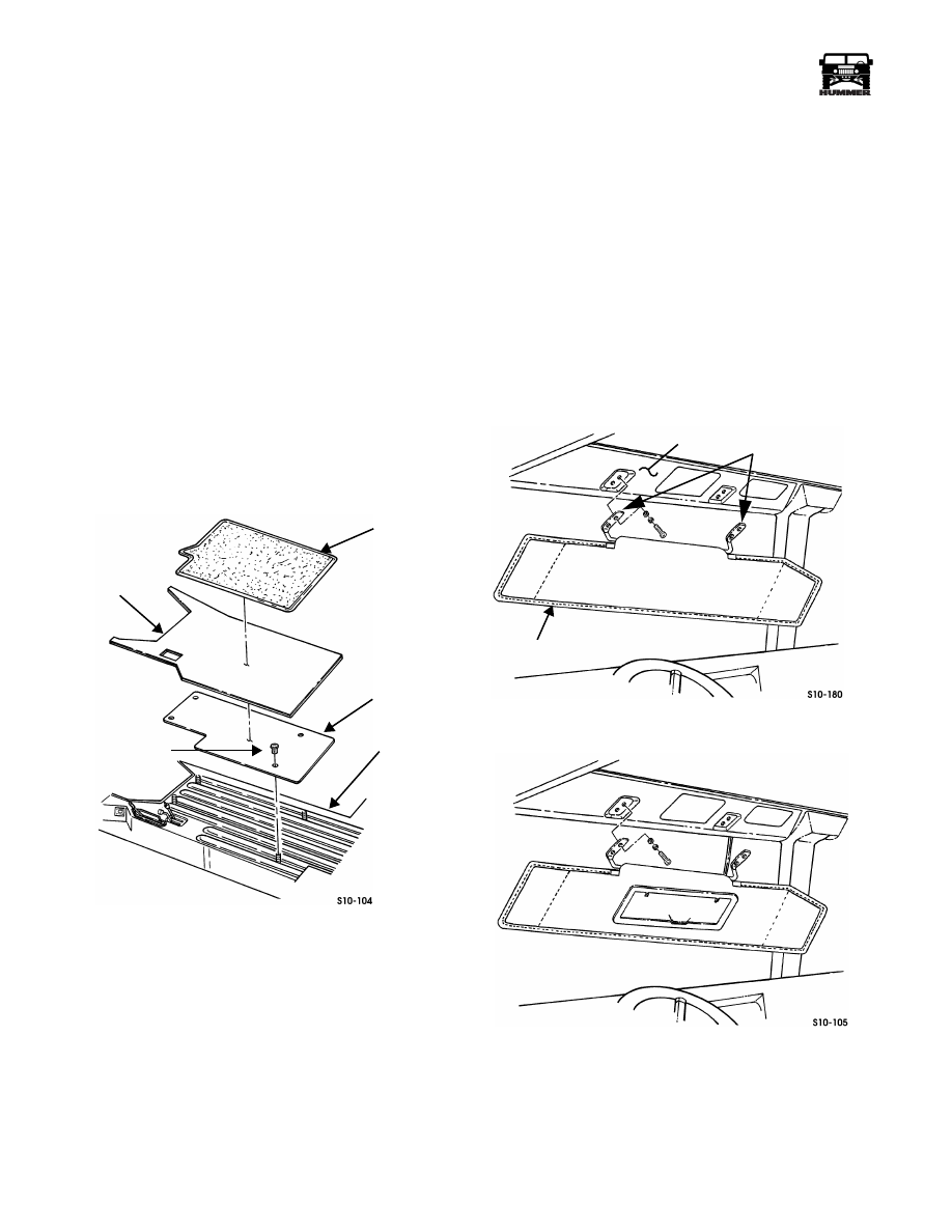
Figure 10-54: Carpet and Padding Installation
VISOR REPLACEMENT
Removal
NOTE:
Visor replacement is the same for each side of the ve-
hicle. This procedure covers the driver’s side.
NOTE:
If your vehicle has the lighted visor mirror, disconnect
the visor mirror lead from the roof harness connector before re-
moving the visor (Figure 10-57).
Remove screws, lockwashers, washers, and visor from body
(Figure 10-57).
Installation
Secure visor mounting brackets to body with four screws, lock-
washers, and washers (Figure 10-57).
Figure 10-55: Visor Mounting
Figure 10-56: Visor With Lighted Mirror
CARPET
PADDING
HARDBOARD
PANEL FASTENER
TUNNEL
VISOR
BODY
MOUNTING
BRACKETS
Нет комментариевНе стесняйтесь поделиться с нами вашим ценным мнением.
Текст