Hummer H1 (2002+). Manual — part 230
_____________________________________________________
Electrical System 12-141
®
05745159
7.
Disconnect green wire connection and remove console.
8.
Disconnect 32 pin connector from amplifier and four screws
securing amplifier to mounting bracket (Figure 12-139).
9.
Remove amplifier.
10. Disconnect 4 pin connector from overhead console
speaker enclosure.
11. Remove speakers and wiring from overhead console
speaker enclosure.
Figure 12-139: Overhead Speaker & Amplifier
Removal.
Installation
1.
Install speakers and wiring in overhead console speaker
enclosure and connect 4 pin connector to audio harness.
2.
Mount amplifier to mounting bracket with four screws and
connect 32 pin connector to audio harness.
3.
Connect dome light wiring and screw overhead console to
roof.
4.
Install windshield divider bar cover.
5.
Install dome light housing and bulb holder with 3 screws,
and dome light lens.
6.
Install upper B-bar cover.
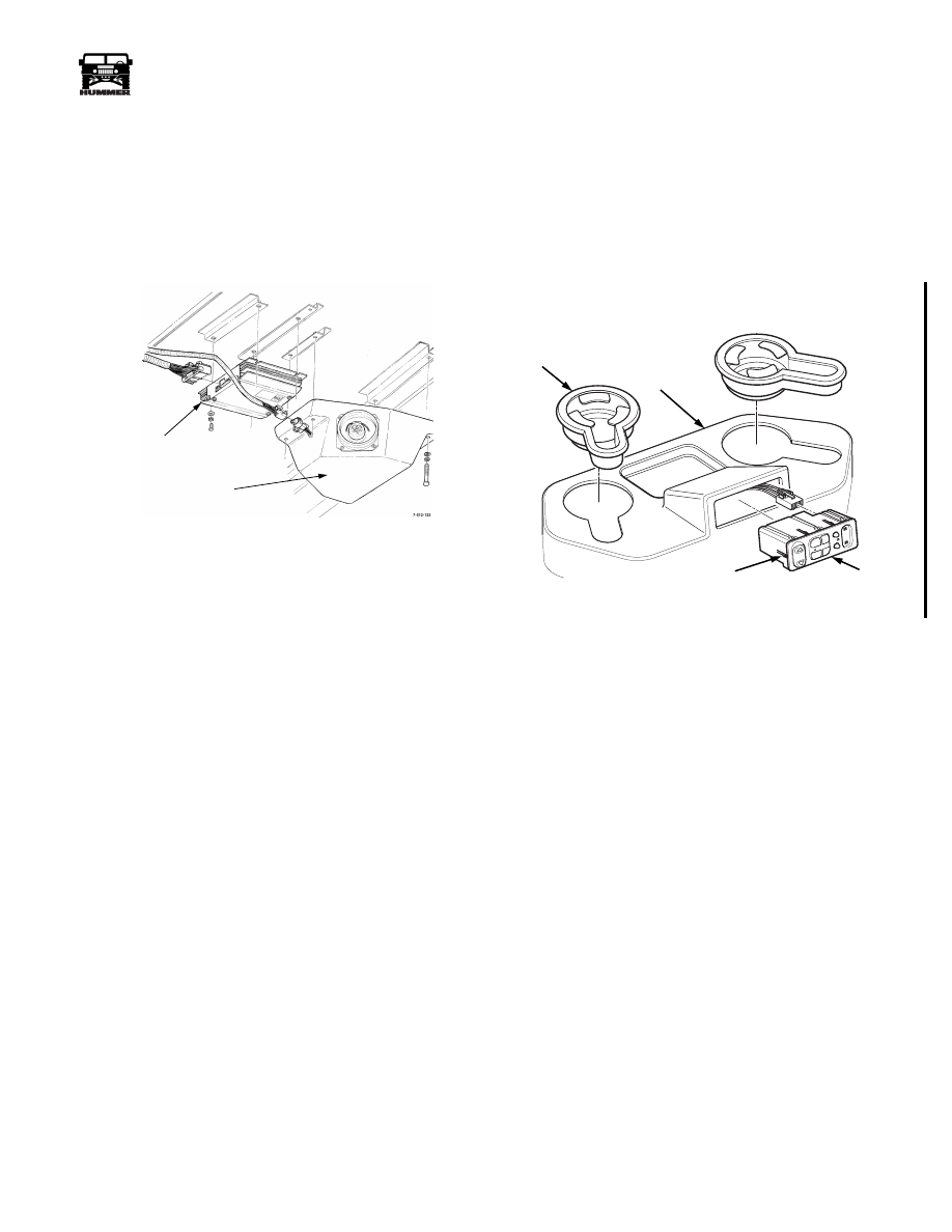
REAR SEAT AUDIO (RSA) UNIT REPLACEMENT
Removal
1.
Remove the cup holders from the auxiliary A/C unit cover
(Figure 12-140).
2.
Reach through the cup holder holes in the cover and
release the tension tabs securing the RSA unit to the cover.
3.
Pull the RSA unit out enough to expose the harness
connector and disconnect the connector.
Figure 12-140: RSA Unit Replacement.
Installation
1.
Connect the harness connector to the RSA unit and insert
into the auxiliary unit cover. Push the RSA unit in until the
tension tabs lock the unit in place.
2.
Press the cup holders in place in the auxiliary unit cover.
SPEAKER ENCLOSURE
AMPLIFIER
OVERHEAD
00-S12-008
VOL
PHO
NES
S EE
K
CD
PW
R
P.SE
T
AM
TAP
E
PRO
G
FM
RSA
UNIT
TENSION
TAB
AUXILIARY
UNIT COVER
CUP
HOLDER
4-1-00
12-142
Electrical System
______________________________________________________
®
AUDIO (DELCO MONSOON) ELECTRICAL
HARNESS
(MODELS 83, 84 & 91) REPLACEMENT
Removal
1.
Remove engine cover console.
2.
Disconnect harness connector from radio head.
3.
Remove Rear Seat Audio (RSA) unit from auxiliary heat
and AC cover console. Disconnect RSA connector from
RSA unit.
4.
Remove four screws, clips, cover, and right front speaker
from trim (Figure 12-141).
5.
Disconnect two leads from right front speaker.
6.
Repeat steps 3 and 4 for left front speaker.
7.
Remove screws from B-bar cover, windshield divider
cover, and overhead console. Disconnect dome light
wiring connections and overhead console speaker
enclosure connector.
8.
Remove four screws, clips, cover, and right rear speaker
from trim.
9.
Disconnect two leads from right rear speaker.
10. Repeat steps 7 and 8 for left rear speaker.
11. Disconnect lead from subwoofer under left rear seat.
12. Remove trim as necessary to gain access to audio harness.
13. Remove audio harness from vehicle.
Installation
1.
Route audio harness to approximate mounting position.
2.
Secure audio harness to vehicle with duct tape, where
necessary.
3.
Connect two leads to right rear speaker.
4.
Install right rear speaker and cover on trim with four clips
and screws.
5.
Repeat steps 3 and 4 for left rear speaker.
6.
Connect lead to subwoofer.
7.
Connect lead to overhead console speaker enclosure.
8.
Connect two leads to right front speaker (Figure 12-141).
9.
Install right front speaker and cover on trim and secure
with four clips and screws.
10. Repeat steps 7 and 8 for left front speaker.
11. Connect harness lead to radio head.
12. Install engine cover console.
13. Connect RSA connector to RSA unit and install RSA unit
in auxiliary heat and AC cover console.
14. Install trim.
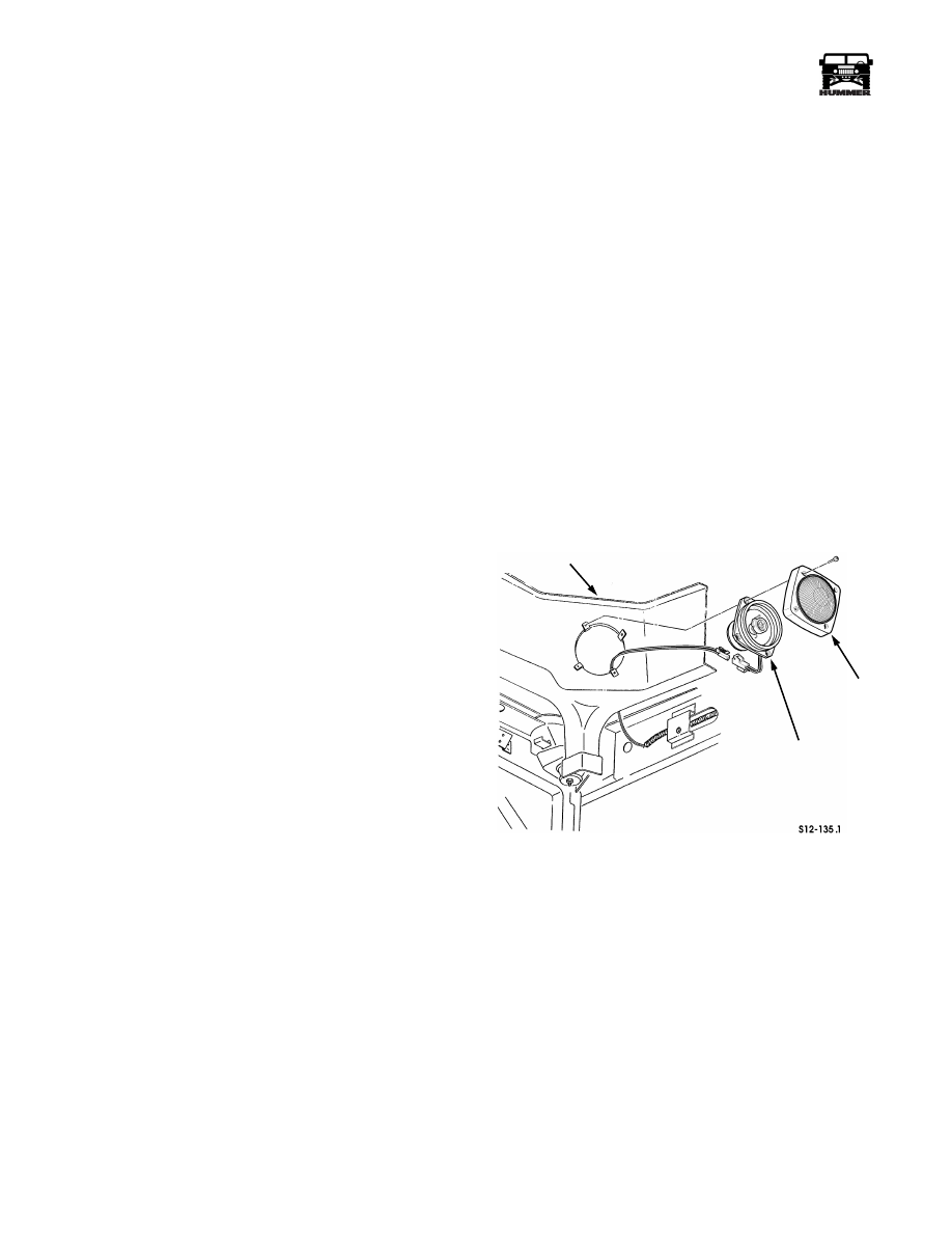
Figure 12-141: Right Front Speaker
Models 83, 84 & 91.
TRIM
COVER
SPEAKER
4-1-00
_____________________________________________________
Electrical System 12-143
®
05745159
AUDIO (DELCO STANDARD) ELECTRICAL
HARNESS (MODEL 89) REPLACEMENT
Removal
1.
Remove engine cover console.
2.
Disconnect radio harness lead from harness connector
(Figure 12-142).
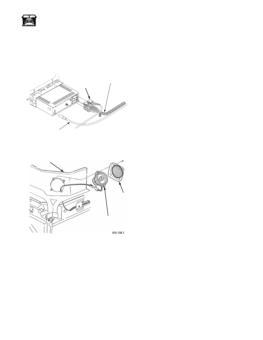
Figure 12-142: Audio Harness Connections.
3.
Remove four screws, clips, cover, and right speaker from
trim (Figure 12-143).
Figure 12-143: Right Front Speaker Model 89.
4.
Disconnect two leads from right speaker.
5.
Repeat steps 3 and 4 for left speaker.
6.
Remove trim as necessary to gain access to audio harness.
7.
Remove audio harness from vehicle.
Installation
1.
Route audio harness to approximate mounting position.
2.
Secure audio harness to vehicle with duct tape, where
necessary.
3.
Install trim.
4.
Connect two leads to right speaker (Figure 12-143).
5.
Install right speaker and cover on trim with four clips and
screws.
6.
Repeat steps 4 and 5 for left speaker.
7.
Connect harness lead to audio harness connector
(Figure 12-142).
8.
Install engine cover console.
AUDIO (DELCO STANDARD) ELECTRICAL
HARNESS (MODELS 83, 84 & 91) REPLACE-
MENT
Removal
1.
Remove engine cover console.
2.
Disconnect harness lead from audio harness connector
(Figure 12-142).
3.
Remove four screws, clips, cover, and right front speaker
from trim (Figure 12-143).
4.
Disconnect two leads from right front speaker.
5.
Repeat steps 3 and 4 for left front speaker.
6.
Remove four screws, clips, cover, and right rear speaker
from trim.
7.
Disconnect two leads from right rear speaker.
8.
Repeat steps 7 and 8 for left rear speaker.
9.
Remove trim as necessary to gain access to audio harness.
10. Remove audio harness from vehicle.
Installation
1.
Route audio harness to approximate mounting position.
2.
Secure audio harness to vehicle with duct tape, where
necessary.
3.
Install trim.
4.
Connect two leads to right rear speaker.
5.
Install right rear speaker and cover on trim with four clips
and screws.
6.
Repeat steps 4 and 5 for left rear speaker.
7.
Connect two leads to right front speaker (Figure 12-143).
8.
Install right front speaker and cover on trim and secure
with four clips and screws.
9.
Repeat steps 7 and 8 for left front speaker.
10. Connect harness lead to audio harness connector.
11. Install engine cover console.
00-S12-006
AUDIO HARNESS
ANTENNA LEAD-IN
CD
HARNESS
COVER
SPEAKER
TRIM
4-1-00
12-144
Electrical System
______________________________________________________
®
AUDIO (DELCO STANDARD) ELECTRICAL
HARNESS (MODEL 90) REPLACEMENT
Removal
1.
Remove engine cover console.
2.
Disconnect harness lead from radio head (Figure 12-142).
3.
Remove four screws, clips, cover, backing plate and right
front speaker from trim (Figure 12-144).
.
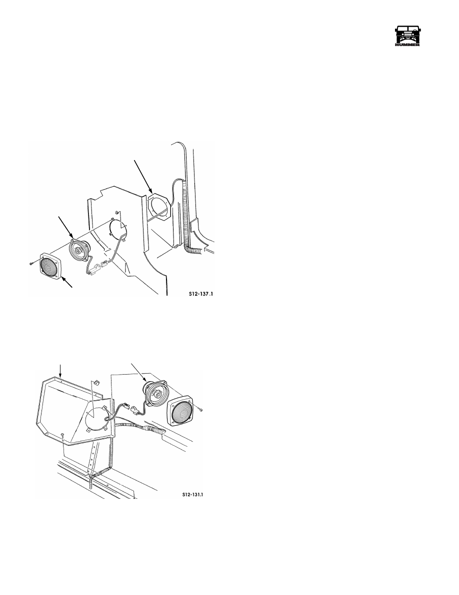
Figure 12-144: Right Front Speaker Model 90.
4.
Disconnect two leads from right front speaker.
5.
Repeat steps 3 and 4 for left front speaker.
6.
Remove four screws, clips, cover, and right rear speaker
from trim (Figure 12-145).
Figure 12-145: Right Rear Speaker Model 90.
7.
Disconnect two leads from right rear speaker.
8.
Repeat steps 7 and 8 for left rear speaker.
9.
Remove trim as necessary to gain access to harness.
10. Remove audio harness from vehicle.
Installation
1.
Route audio harness to approximate mounting position.
2.
Secure harness to vehicle with duct tape, where necessary.
3.
Install trim.
4.
Connect two leads to right rear speaker (Figure 12-145).
5.
Install right rear speaker and cover on trim and secure with
four clips and screws.
6.
Repeat steps 4 and 5 for left rear speaker.
7.
Connect two leads to right front speaker (Figure 12-144).
8.
Install right front speaker and cover on trim with four clips
and screws.
9.
Repeat steps 7 and 8 for left front speaker.
10. Connect harness lead to radio head.
11. Install engine cover console.
DIAGNOSIS -DELCO AUDIO SYSTEM
1.
Verify customer complaint.
2.
Follow radio service procedures.
3.
If technical service is required, have all the pertinent
information ready before placing the call.
NOTE:
Before performing any diagnostic procedures or using
any diagnostic tools, check wiring schematics for component
circuitry to determine the location of fuses and circuit breakers
in the circuit. Fuses and circuit breakers must be in good work-
ing order to perform proper diagnostic procedures.
Delco Audio System Diagnostic Kit J–39916-A is available
from Kent-Moore. The kit contains a diagnostic CD and cas-
sette, a head cleaner cassette and instructions. This kit is de-
signed to isolate the type of malady and the area of its origin by
producing tones of various frequencies. By adjusting the fade
and balance, a technician can evaluate the sound quality pro-
duced in different areas of the system.
Identifying Concerns
• Check for technical service bulletins.
• For reception concerns, determine if the station is ob-
tainable in the customers listening area.
• To test for audio reception/noise, position the vehicle
outside the building with the hood down.
• Duplicate the customers complaint before trying to di-
agnose the system. Have the customer demonstrate the
condition. Test drive the vehicle with the customer and
then test drive another similar model vehicle (with a
similar audio system) to do a comparison of the two ve-
hicles to determine if the condition is abnormal.
• Before diagnosing, identify components, their features
and the customer’s complaint.
• Determine if any aftermarket equipment is installed on
the vehicle. Disconnect the aftermarket equipment and
determine if the customers complaint still exists.
• Perform the following steps to identify a noisy component:
BACKING PLATE
SPEAKER
COVER
TRIM
SPEAKER
4-1-00
Нет комментариевНе стесняйтесь поделиться с нами вашим ценным мнением.
Текст