Hummer H1 (2002+). Manual — part 231
_____________________________________________________
Electrical System 12-145
®
05745159
1.
Identify ignition switch key position in which the noise
appears, such as: accessory, key on engine not running,
and key on engine running.
2.
Remove fuses one at a time until the complaint condition
has been eliminated.
3.
Mark the complaint fuse(s) and reinstall all fuses and
circuit breakers.
4.
Identify all systems and components powered by the
complaint fuse(s).
5.
Disconnect the components powered by the complaint
fuse(s) one at a time until the complaint condition has
been eliminated and the noisy component has been
identified.
6.
Check the ground integrity of the complaint causing
component.
• An interference condition is not necessarily an audible
noise.
• Most noises can be found on weak stations near the low
end of the band and are considered to be a normal condi-
tion.
• Malfunctioning and marginal components, relays, and
solenoids may induce noise and/or poor reception.
7.
Check for a broken (or partially broken) wire inside of the
insulation which could cause system malfunction but
prove “good” in a continuity/voltage check with a system
disconnected. These circuits may be intermittent or
resistive when loaded, and if possible, should be checked
by monitoring for a voltage drop with the system
operational (under load).
Corrective Action
• Use proper tools for diagnostics and repairs.
• Follow electrical system diagnostic guidelines.
• Use available noise suppression devices:
—Filter package P/N 05744279
Utilize the test tape /CD Diagnostic Kit Kent-Moore
P/N J–39916-A to optimize proper audio diagnostics.
• If the condition requires the radio to be sent to the ser-
vice center, describe the symptoms on the warranty
form exactly.
• Do not leave a CD disc or tape in the vehicle. Extreme
heat could cause permanent damage.
• Cassette tapes could be damaged if not stored in the
case. The vibration in the vehicle can cause the tape to
unwind inside the cartridge.
• Use available trouble trees.
• Before removing speaker(s), check all connectors and
wiring to the speakers. Examine the connectors for bent
or loose pins. Refer to troubleshooting procedures.
• If a test antenna is used in diagnostics, ground the an-
tenna base to the vehicle body and do not hold the mast.
NOTE:
Check the antenna coax connectors for corrosion or
bad connections/crimps. Route coax separately from the other
wires. Shield antenna coax interconnections with aluminum or
nickel tape. Check all vehicle grounds, not just antenna and ra-
dio grounds. Refer to the antenna diagnostic section.
• Coated screws or bolts can act as poor grounds.
• Always use a braided ground strap when applying
grounds. Keep the ground strap as short as possible, the
shorter the ground strap the better.
• When shielding the dash, wires, hoses (most hoses are
conductive unless they have a white stripe), use alumi-
num foil tape or nickel tape to shield against magneti-
cally induced interference. For optimum performance
try varying the following ground techniques:
—Add a ground at both ends of the tape.
—Add a ground to just one end of the tape.
—Do not add ground to the tape.
• When shielding a harness with tape, attach a ground
strap to the end of the tape and then wrap the strap 360
degrees around the tape securing the other end of the
strap to a known good chassis ground.
• Any interference is best corrected by suppression at the
source of the interference, if possible.
• Care should be used when applying suppression. Signal
wires (such as sensor outputs, clock, and communica-
tion circuits) cannot be suppressed. After adding any
suppression, all vehicle systems (even those not related
to the audio system) should be checked for proper oper-
ation and function.
• Interference can usually be eliminated by shielding/
grounding or suppressing.
• Capacitors work best on switch pops and low frequency
noise. Filters work best on high frequency whines and
static.
• Whenever possible, make a test harness that includes fil-
ters and capacitors. Always check the effectiveness and
operation before permanently installing a fix.
• Recommended capacitor application for an audible pop
induced from a switching operation is:
—Add a capacitor across the contacts of the switch.
—Add a capacitor from the hot side of the switch to
ground.
—Add a capacitor to each side of the switch to
ground.
• If a complaint condition is only present with the ignition
key in the run position and the engine running, perform
the following checks:
—Check the integrity of the engine compartment
grounds.
—Check for malfunctioning relays, solenoids, or
other components which may be inducing “noise”
or poor reception.
—Check the ground integrity of the complaint caus-
ing component.
• For noise and/or poor reception, perform the antenna
system test and make the necessary repairs.
4-1-00
12-146
Electrical System
______________________________________________________
®
TEST ANTENNA
The test antenna is simply an antenna that is not mounted on
the vehicle. This tool is used as a substitute for the antenna
mounted on the vehicle. The technician should connect the test
antenna to the antenna input of the radio. Ground the base of
the antenna to the vehicle’s chassis.
Do not hold the mast of
the antenna.
This will decrease the capability of the antenna to
receive a station.
GENERATOR WHINE CONCERNS
• Check the ground terminal on the battery.
• Check for coated mounting bolts on the generator
bracket.
• Check for a faulty mounting of the generator to the en-
gine.
• Make sure grounds at starter and intake manifold are
clean and tight.
• Try the following:
1.
If noise is still present, check the charging system.
2.
If the charging system is functioning normally, check for
technical service bulletins on generator whine.
3.
Install a filter P/N 05744279 in the battery feed to the
radio.
4.
Try installing the filter with the following variations if the
noise is not eliminated.
a.
Install the filter with the single wire side toward the
radio and the ground wire attached to a good ground.
b.
Remove the ground to the filter.
c.
Reverse the filter so the two wire side is toward the
radio with the ground wire attached to a good ground.
d.
Remove the ground from the filter.
5.
If the noise is still present, install another filter P/N
05744279 in the ignition feed to the radio. Install using the
same variations as the first filter. If the installation of this
filter causes turn on or turn off delays or other noticeable
performance concerns, remove it and install a 0.47 mf
(microfarad) capacitor in its place.
6.
Remove any unneeded filters after repair, before
reassembling the vehicle.
4-1-00

_____________________________________________________
Electrical System 12-147
®
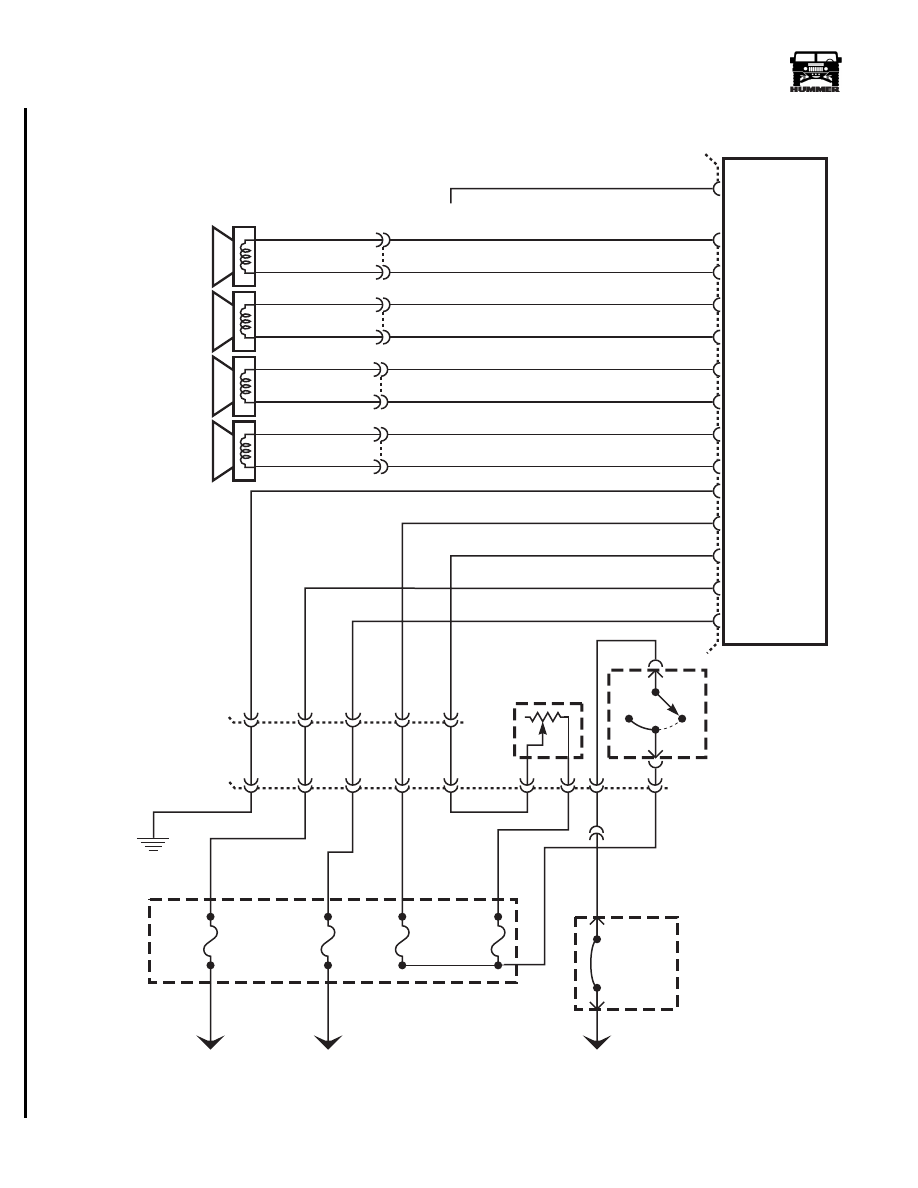
05745159
Figure 12-146: Monsoon Audio Harness Schematic Models 83, 84 & 91.
BK
RD
BK
TN
B
A
LF SPEAKER
E16
E15
BK
RD
BK
TN
B
A
RF SPEAKER
F2
F3
BK
RD
BK
BK
TN
B
RD
A
B
A
LEFT CONSOLE SPKR
F6
F7
BK
RD
BK
BK
TN
B
RD
A
B
A
RIGHT CONSOLE SPKR
E13
E14
BK
RD
BK
TN
B
A
LR SPEAKER
F16
F15
BK
RD
BK
TN
B
A
RR SPEAKER
F13
F14
RD
RD/BK
TN
BK
B
A
FRONT SUB WOOFER
F11
F10
RD
RD/BK
TN
BK
B
A
REAR SUB WOOFER
F5
F4
DG
PK
15
E6
16
E7
9
E5
10
E4
18
F8
8
3
E11
E12
4
7
E8
20
E9
AMPLIFIER
11
E1
12
F1
13
E2
14
E3
C57
C62
C56
6
BK
C59
A1
A2
A3
A4
A5 A8
B5
B6
B8
REAR SEAT AUDIO
E10
22
19
BATT 12V
GROUND
–
+
–
+
–
+
–
+
–
+
–
+
+
–
+
–
RADIO
RSA ENABLE
BATT 12V
DIMMER
ILLUMINATION
GROUND
CELL PHONE
MUTE
LF
LF
RF
RF
RR
RR
LR
LR
AMPLIFIER
SENSE
–
+
–
+
–
+
–
+
IGNITION
RSA CONTROL
C3
INTERNAL
FUSE BOX
00-S12-001
PANEL
LIGHT
DIMMER
OFF
HEAD
PARK
2
1
476 GY
59 BK
FUSE
1D
15 AMP
FUSE
1F
5 AMP
N9
J6
C1
B4 G3
F3
C60
C
H
G
B
A
E
D
CIRCUIT
BREAKER
#2
30 AMP
FUSE
4G
7.5 AMP
FUSE
2H
10 AMP
H9
K7
FUSE
2F
5 AMP
EXTERNAL
FUSE BOX
137 RD
829 LG
14 LB
19 YL
H6
B1
37 RD
297 OR
37 RD
TO BATTERY
TO BATTERY
TO IGNITION
14 LB
17 PP
38 RD
C1-67
C62
HEADLIGHT
SWITCH
839 YL
820 DG
821 BK
818 PP
819 BK
830 PK
17 PP
14 LB
59 BK
137 RD
476 GY
805 GY
811 BK
804 WT
813 BK
59 BK
829 LG
833
834
835
836
837
838
831
832
801
800
803
802
827
826
825
824
4
Ω
4
Ω
4
Ω
4
Ω
4
Ω
4
Ω
2
Ω
2
Ω
842 OR
137 RD
843 GY
820 DG
821 BK
818 PP
819 BK
59 BK
14 LB
843 GY
842 OR
842 OR
G4
3-1-01
12-148
Electrical System
______________________________________________________
®
.
Figure 12-147: Standard Audio Harness Schematic Models 83, 84, 90 & 91.
OFF
HEAD
PARK
2
1
PANEL
LIGHT
DIMMER
476 GY
59 BK
FUSE
1F
5 AMP
J6
C1
B4
G3
F3
C
B
A
E
D
CIRCUIT
BREAKER
#2
30 AMP
FUSE
4G
7.5 AMP
FUSE
2H
10 AMP
H9
K7
FUSE
2F
5 AMP
EXTERNAL
FUSE BOX
137 RD
14 LB
19 YL
H6
B1
37 RD
297 OR
TO BATTERY
TO BATTERY
TO IGNITION
14 LB
17 PP
38 RD
C1-67
HEADLIGHT
SWITCH
G4
BK
RD
B
A
RR SPEAKER
BK
RD
B
A
LR SPEAKER
BK
RD
B
A
LF SPEAKER
BK
RD
B
A
15
16
9
10
8
3
6
4
7
20
RADIO
IGNITION
BATT 12V
DIMMER
ILLUMINATION
GROUND
CELL PHONE
MUTE
11
12
13
14
LF
LF
RF
RF
RR
RR
LR
LR
C56
C57
–
+
–
+
–
+
–
+
819 BK
818 TN
821 BK
820 TN
813 BK
804 TN
811 BK
805 TN
839 YL
17 PP
14 LB
137 RD
476 GY
59 BK
INTERNAL
FUSE BOX
00-S12-039
C3
C60
4
Ω
4
Ω
4
Ω
4
Ω
RF SPEAKER
3-1-01
Нет комментариевНе стесняйтесь поделиться с нами вашим ценным мнением.
Текст