Hummer H1 (2002+). Manual — part 228
___________________________________________________
Electrical System 12-134.3
®
05745159
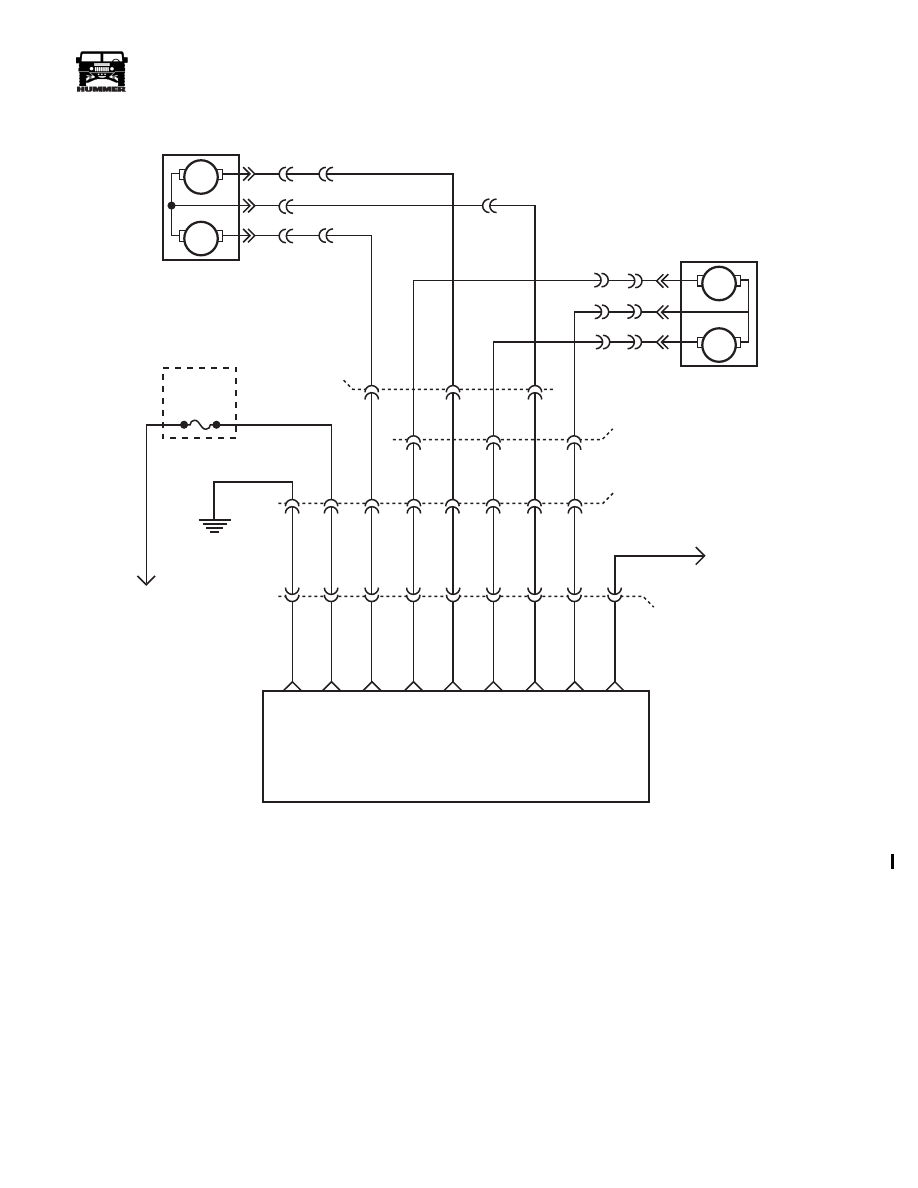
Figure 12-131: Power Side Mirror Schematic
59 BK
1
2
3
4
5
6
7
8
9
M
M
LH POWER MIRROR
M
M
RH POWER MIRROR
FUSE
3H
20 AMP
517 PK
948 DG/
YL
953 DG
947 DG/
YL
952 DB
942 OR/ BK
944 OR
17 PP
TO
DIMMER
MODULE
POWER MIRROR SWITCH
LH UP
/ DOWN
RH UP
/ DOWN
RH LEFT / RIGHT
LH LEFT / RIGHT
G4
TO
BATTERY
C23
GROUND
BA
TTER
Y
FEED
COMMON
COMMON
SWITCH ILLUM
9-S12-010
J
H
F
E
B
C
D
G
G1
C3
J8
M9
J9
L8
K6
K8
C25
A
B
C
C24
C
B
A
A
INTERIOR
FUSE BOX
N6
3-1-01
12-134.4
Electrical System
____________________________________________________
®
CRUISE CONTROL SYSTEMS
WARNING: Testing of cruise control should only be
preformed in areas were traffic is light and the road
conditions are stable.
Figure 12-130.1 : Cruise Control
Operation of Cruise Control
1.
Move the cruise control switch to the “ON” position.
2.
Accelerate to the desired speed.
3.
Push in the “SET” button on the end of the turn signal
lever and release it at the desired speed. This will set the
vehicle speed.
NOTE:
The vehicle speed will decrease
while the “SET” button is pushed in
.
The cruise control will not operate under 35 MPH.
Accelerating with the Cruise Control On
Vehicle speed can be momentarily increased after the desired
speed has been set. By pressing the accelerator pedal the speed
will increase. This action will not interfere with the preset
cruising speed. The preset speed will resume after the accelera-
tor pedal is released.
Resetting the Cruise Control to a Higher Speed
There are two ways to reset the cruise control to a higher
speed.
1.
Press the accelerator pedal until the desired speed is
reached. Push the “SET” button and release it. Speed
should set like normal.
2.
Move the cruise control switch from “ON” to “R/A”. Hold
the switch in place until you reach the desired speed and
then hold the control switch in the “R/A” position for half
a second and release. Each time this is done the vehicle
speed will increase by 1 MPH.
Turning Off the Cruise Control
There are two ways to turn the cruise control off while driving:
1.
Move the cruise control switch to the “OFF” position.
2.
Depress the brake pedal slightly. This turns off the cruise
control operation. but does not erase the speed memory.
To resume cruise control after touching the brake pedal,
follow the instructions under “Resuming a set Speed”.
In addition, the cruise control is automatically disabled each
time you turn the engine off, Or shift into “P” (Park) “N” (Neu-
tral) position, or if the “Check Throttle Light” is illuminated.
Resuming a Set Speed
If the cruise control was turned off by depressing the brake
pedal slightly, move the cruise control switch from “ON” to
“R/A” and hold for approximately one second and release. The
vehicle will gradually return to the previously set speed and
maintain it.
Resuming a set speed will not function if the cruise control was
turned off using the cruise control switch, or if the vehicle
speed is below cruise control minimum (35 MPH).
Using Cruise Control on Hills
Driving on a hill can affect the performance of the cruise con-
trol. This performance can be greatly affected if the vehicle is
loaded or towing a trailer. Use of the accelerator pedal will
help maintain vehicle speed but brakes will turn cruise off. If
vehicle speed is being significantly reduced or increased when
using the cruise control on a hill, turn the cruise control off
and manually control the vehicle speed.
Inspection
When working on the cruise control system make sure that
there are no other problems with the PCM or fueling system.
Always road test and verify the problem before attempting any
repairs.
Intermittent problems
All of the charts in this section are for use on current failures.
Do not attempt to use these charts to diagnose a problem unless
the problem has been verified and currently exists. If the prob-
lem is intermittent, parts will be replaced, or no problem will
be found.
9-OM2-031
3-1-01

_____________________________________________________
Electrical System 12-135
®
05745159
Cruise Control Inoperative VIN Z
Step
Action
Value(s)
Yes
No
1
Important: Before clearing the DTC’s, use the
scan tool Capture Info in order to record the
Freeze Frame and the failure records for refer-
ence, as the data will be lost when the Clear Info
function is used.
Was the Powertrain On-Board Diagnostic (OBD)
System check performed?
Go to step 2.
Perform on-
board diagnos-
tic system check.
2
Disconnect cruise control lever from cross body
harness under dash. Using a DVOM set to mea-
sure resistance, Probe the BRN wire with the neg-
ative lead and the RD wire with the positive lead.
Turn the cruise on\off switch to “on”. Does the
resistance meet specification?
<.2
Ω
Go to step 3.
Replace cruise
control arm.
3
Leave the negative lead in the BRN wire, place
the positive lead in the YL wire. With the resume
switch in the neutral position, the switch should
be open. When the resume switch is moved to the
spring loaded position, the switch should close
and meet the resistance specification?
neutral-open
closed<.2
Ω
Go to step 4.
Replace cruise
control arm.
4
Leave the negative lead in the BRN wire, place
the positive lead in the GRN wire. With the set
switch in the neutral position, the meter should
display an open, with the switch pushed in the
meter should display continuity, does it?
neutral-open
closed<.2
Ω
Go to step 5.
Replace cruise
control arm.
5
Connect scan tool to vehicle, locate cruise control
On/Off switch in the engine data list. When the
switch is moved on and off, does the engine data
list reflect the change?
Go to step 6.
Go to step 9.
6
Locate resume/accel switch in engine data list.
When the switch is moved to the resume/accel
position, does the engine data list reflect the
change?
Go to step 7.
Go to step 10.
7
Locate set/coast in engine data list. When the
switch is pushed, does the data list reflect the
change?
Go to step 8.
Go to step 11.
8
Locate the brake switches in the engine data list,
depress the brake pedal, does the data list reflect
the change?
Check for loose
or poor connec-
tion at PCM if
none are found
replace the PCM.
Go to step 16.
4-1-00
Section 12 Electrical System

12-136
Electrical System
______________________________________________________
®
9
Using a DVOM set to measure voltage, place the
ground lead on the IP ground point. Back probe
cavity A11 in C29(CKT151) with the positive
lead. With the ignition on and the cruise control
switch on, is voltage present?
12v
Check for loose
or poor connec-
tion at PCM if
none are found
replace the PCM.
Repair open, bad
connection or
short to ground
in CKT151
between the
PCM and cruise
control arm.
10
Using a DVOM set to measure voltage, place the
ground lead on the IP ground point. Back probe
cavity D10 in C27(CKT153) with the positive
lead. With the ignition on and the cruise control
resume/accel button depressed, is voltage
present?
12v
Check for loose
or poor connec-
tion at PCM if
none are found
replace the PCM.
Repair open, bad
connection or
short to ground
in CKT153
between the
PCM and cruise
control arm.
11
Using a DVOM set to measure voltage, place the
ground lead on the IP ground point. Back probe
cavity B11 in C29(CKT152) with the positive
lead. With the ignition on and the cruise control
set button depressed
12v
Check for loose
or poor connec-
tion at PCM if
none are found
replace the PCM.
Repair open, bad
connection or
short to ground
in CKT152
between the
PCM and cruise
control arm.
12
Using a DVOM set to measure voltage, place the
ground lead on the IP ground point. Back probe
cavity B10 in C29(CKT22) with the positive lead.
Depress the brake switch. Is voltage present?
12v
go to step 13.
Check for open
or short to
ground/voltage
in CKT 22, if
none found
replace brake
switch.
13
Using a DVOM set to measure voltage, place the
ground lead on the IP ground point. Back probe
cavity B9 in C29(CKT810) with the positive lead.
With the ignition on, is voltage present with the
brake NOT applied, and disappear when the brake
is depressed?
Brake OFF 12v
Brake ON 0v
Check for loose
or poor connec-
tion at PCM if
none are found
replace the PCM.
Check for open
or short to
ground/voltage
in CKT 810, if
none found
replace brake
switch.
Cruise Control Inoperative VIN Z (Continued)
Step
Action
Value(s)
Yes
No
4-1-00
Нет комментариевНе стесняйтесь поделиться с нами вашим ценным мнением.
Текст