Hummer H1 (2002+). Manual — part 283

_____________________________________________________
PCM/Tech 1 Scan Tool 65
®
05745159
DTC P0228 - Accelerator Pedal Position (APP) Sensor 3 Circuit High Voltage
Step
Action
Value(s)
Yes
No
1
Important:
Before clearing DTC(s) use the scan tool “Capture Info” to
record Freeze Frame and Failure Record for reference, as data will be lost
when “Clear Info” function is used.
Was the “On-Board Diagnostic (OBD) System Check” performed?
—
Go to Step 2.
Go to OBD
System Check.
2
1. Ignition “ON”, engine “OFF”.
2. With the throttle closed, observe APP 3 display on the scan tool.
Is APP 3 above the specified value?
4.75v
Go to Step 4. Go to Step 3.
3
DTC is intermittent. If no additional DTCs are stored, refer to “Diagnostic
Aids”. If additional DTCs were stored, refer to those chart(s).
Are additional DTCs stored?
—
Go to the
applicable
DTC table.
Go to
Diagnostic
Aids.
4
1. Disconnect the APP sensor electrical connector.
2. Observe the APP 3 display on the Scan Tool.
Is APP 3 less than or equal to the specified value?
—
Go to Step 5. Go to Step 7.
5
Probe APP 3 sensor ground circuit at the APP sensor harness connector
with a test light connected to B+.
Is the test light “ON”?
0.25v
Go to Step 8.
Go to Step 6.
6
1. Check for a short to voltage on the APP 3 sensor signal circuit.
2. If the APP 3 sensor signal circuit is shorted, repair it as necessary.
Was the APP 3 sensor signal circuit shorted?
—
Go to Step 11. Go to Step 10.
7
1. Check for an open sensor ground circuit.
2. If a problem is found, repair as necessary.
Was APP 3 sensor ground circuit open?
—
Go to Step 11. Go to Step 10.
8
Check for poor electrical connections at the APP sensor and replace termi-
nals if necessary.
Did any terminals require replacement?
—
Go to Step 11.
Go to Step 9.
9
Replace the APP module.
Is Action complete?
—
Go to Step 11.
—
10
Replace the faulty PCM. Notice: If the PCM is faulty, the new PCM must
be programmed. Go to PCM replacement and programming procedures.
Is the action complete?
—
Go to Step 11.
—
11
1. Using the Scan Tool, select “DTC”, “Clear Info”.
2. Start engine and idle at normal operating temperature.
3. Select “DTC”, “Specific”, then enter the DTC number which was set.
4. Operate vehicle within the conditions for setting this DTC as specified in
the supporting text.
Does the Scan Tool indicate that this diagnostic Ran and Passed?
—
Go to Step 12.
Go to Step 2.
12
Using the Scan Tool, select “Capture Info”, “Review Info”.
Are any DTCs displayed that have not been diagnosed?
—
Go to the
applicable
DTC table
System OK

66
PCM/Tech 1 Scan Tool
_____________________________________________________
®
DTC P0231 Fuel Lift Pump Secondary Circuit
Low Voltage
Circuit Description
The status of the lift pump is monitored by the PCM. This sig-
nal is also used to store a DTC if the fuel pump relay is defec-
tive or fuel pump voltage is lost while the engine is running.
There should be about 12 volts on circuit 120 during glow plug
cycle. This is a Type B DTC.
Conditions for Setting the DTC
• Fuel lift pump commanded “ON”.
• Ignition voltage minus 4 volts.
• Fuel lift pump voltage less than ignition voltage value.
• Conditions met for 2 seconds.
Action Taken When the DTC Sets
No action taken.
Conditions for Clearing the MIL/DTC
• The PCM will turn the MIL off after three consecutive
trips without a fault condition.
• A History DTC will clear when forty consecutive
warm-up cycles that the diagnostic does not fail (coolant
temperature has risen 5°C (40°F) from start up coolant
temperature and engine coolant temperature exceeds
71°C (160°F) that same ignition cycle).
• Use of a Scan Tool
Diagnostic Aids
This DTC will not check the fuel pump operation.
Test Description
Number(s) below refer to the number(s) on the diagnostic ta-
ble.
3. This step will check the fuel pump circuit.
FUSE 2D
20A
INTERIOR
FUEL PUMP
RELAY
EXTERIOR
FUSE BOX
C1-10
G2
POWERTRAIN
CONTROL
MODULE
FUEL PUMP
RELAY CONTROL
FUEL LIFT
PUMP SIGNAL
TO FUEL
SELECTOR SWITCH
M
G2
FUEL
LIFT
PUMP
B
A
57 BK
787 GY
787 GY
787 GY
C27-D5
57 BK
C27-D8
238 DG
537 OR
9-S12-051
9-S12-051

_____________________________________________________
PCM/Tech 1 Scan Tool 67
®
05745159
DTC P0231 - Fuel Lift Pump Secondary Circuit Low Voltage
Step
Action
Value(s)
Yes
No
1
Important:
Before clearing DTC(s) use the scan tool “Capture Info”.
Was the “On-Board Diagnostic (OBD) System Check” performed?
—
Go to Step 2. Go to OBD Sys-
tem Check.
2
1. Turn the ignition “OFF” for 20 seconds.
2. Turn the ignition “ON”.
3. Listen for the fuel lift pump.
Does the lift pump operate during glow plug cycle and then turn “OFF”?
—
Go to
Diagnostic
Aids.
Go to Step 3.
3
1. Turn the ignition “OFF”.
2. Probe the fuel pump test terminal with a fused jumper to “B+”.
Does the fuel pump operate?
—
Go to Step 8.
Go to Step 4.
4
1. Disconnect the fuel pump relay.
2. Probe the fuel pump test terminal with a fused jumper to “B+”.
Does the fuel pump operate?
—
Go to Step 5. Go to Step 6.
5
Replace the faulty fuel pump relay.
Is the action complete?
—
Go to Step 6.
—
6
Check for a an open fuel pump signal circuit.
Was a problem found?
—
Go to Step 7.
Go to Step 8.
7
Repair the open fuel pump signal circuit.
Is the action complete?
—
Go to Step 8.
—
8
1. Turn the ignition “OFF”.
2. Remove the fuel pump relay.
3. Connect a test light to ground.
4. Probe the fuel pump relay harness connector terminal number “B1”.
Is the test light “ON”?
—
Go to Step 10.
Go to Step 9.
9
Repair the open in the battery feed circuit to the fuel pump relay.
Is the action complete?
—
Go to Step 10.
—
10
Connect a test light between terminal number “B1” and terminal number
“A1” of the fuel pump relay harness connector.
Is the test light “ON”?
—
Go to Step 12. Go to Step 11.
11
Repair the open fuel pump relay ground circuit.
Is the action complete?
—
Go to Step 12.
—
12
1. Turn the ignition “OFF”.
2. Connect a test light between terminal number “B3” and ground.
3. Monitor the test light.
4. Turn the ignition “ON”.
Was a problem found?
—
Go to Step 16. Go to Step 13.
13
Check for an open in circuit from fuel pump relay harness connector termi-
nal number “B3” and PCM.
Was a problem found?
—
Go to Step 14. Go to Step 15.
14
Repair the open in the fuel pump relay control circuit.
Is the action complete?
—
Go to Step 15.
—
15
Replace the faulty PCM. Notice: If the PCM is faulty, the new PCM must
be programmed. Go to PCM replacement and programming procedures.
Is the action complete?
—
Go to Step 16.
—
16
Check for a faulty connection at fuel pump relay harness connector terminal
number “B3”.
Was a problem found?
—
Go to Step 18. Go to Step 17.
17
Replace the faulty fuel pump relay.
Is the action complete?
—
Go to Step 18.
—
68
PCM/Tech 1 Scan Tool
_____________________________________________________
®
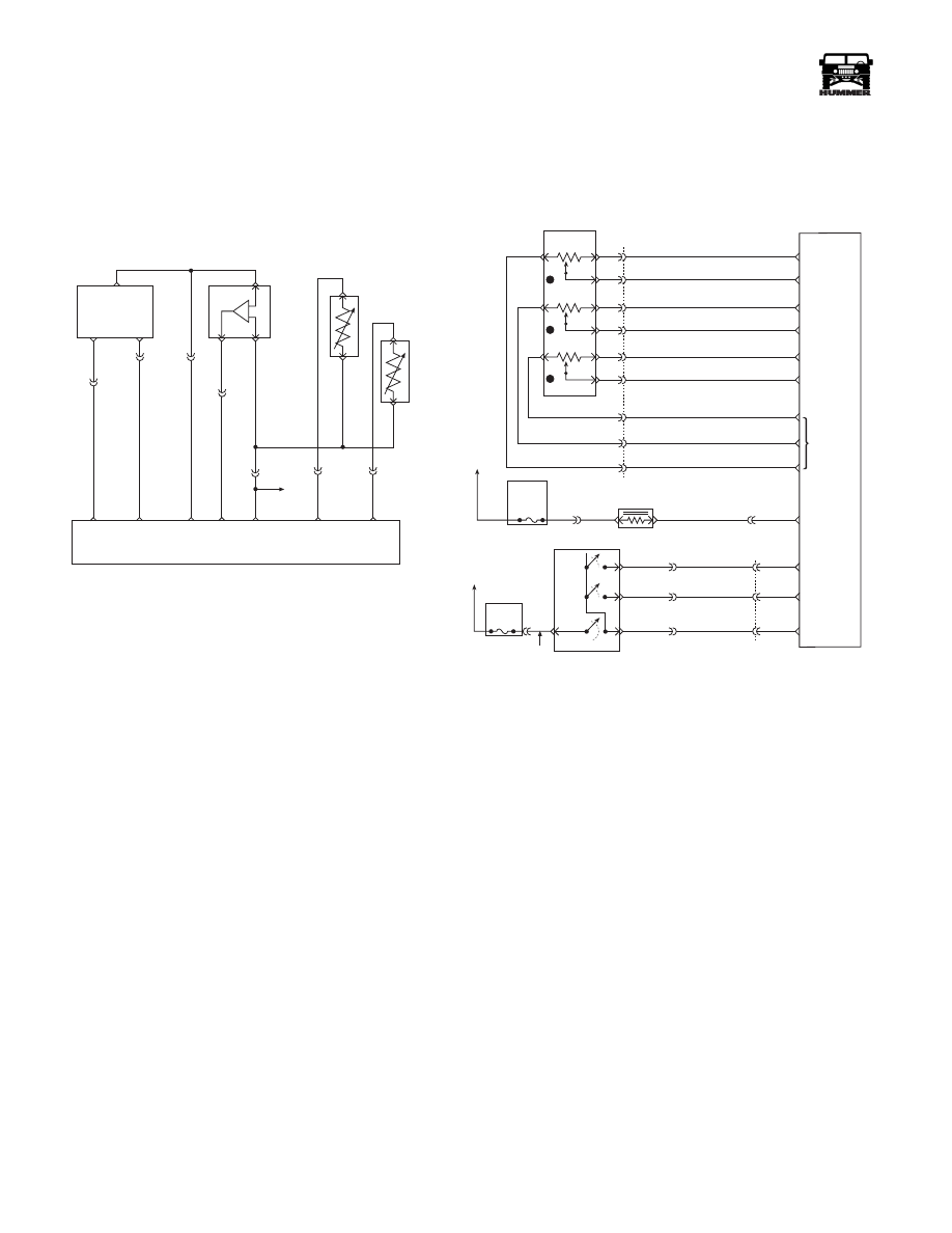
DTC P0236 Turbocharger (TC) Boost System
Circuit Description
The PCM operates a solenoid to control boost. This solenoid is
normally open. By providing a ground path the PCM energizes
the solenoid which then allows vacuum to pass to the waste-
gate valve. During normal operation, the PCM compares its
wastegate duty cycle signal with the boost signal and makes
corrections in the duty cycle accordingly. This is a type B
DTC.
Conditions for Setting the DTC
• Engine speed greater than 2400 RPM.
• Fuel rate greater than 20 mm.
• Boost pressure less than or equal to 20 kPa from desired
(internal to PCM).
• Conditions met for 10 seconds.
or
• Engine speed greater than 1800 but less than 2400 RPM.
• Fuel rate greater than 20 mm.
• Boost pressure less than or equal to (110 kPa) - ((100
kPa - Baro)/2) (internal to PCM).
• Conditions met for 2 seconds.
Action Taken When the DTC Sets
• Poor performance.
• Reduce maximum fuel.
• No TCC.
Conditions for Clearing the MIL/DTC
• The PCM will turn the MIL off after three consecutive
trips without a fault condition.
• A History DTC will clear when forty consecutive
warm-up cycles that the diagnostic does not fail (coolant
temperature has risen 5°C (40°F) from start up coolant
temperature and engine coolant temperature exceeds
71°C (160°F) that same ignition cycle).
• Use of a Scan Tool.
Diagnostic Aids
A vacuum leak or a pinched vacuum line may cause a DTC
P0236. Check all vacuum lines and components connected to
the hoses for leaks or sharp bends. Check vacuum source. A
possible EGR DTC will store if there is a problem with the
vacuum source. Also check for proper vacuum line routing.
This diagnostic checks for a “skewed” sensor.
Test Description
Number(s) below refer to the number(s) on the diagnostic ta-
ble.
This will check the Boost sensor scaling. One step will check
the scaling with vacuum applied and one without.
5 VOLT
REFERNCE
CKP
SENSOR
SIGNAL
SENSOR
GROUND
CRANK
SHAFT
POSITION
SENSOR
(CKP)
A
B
B
A
B
B
A
A
C
C
C5-B12
C5-B5
C5-B9
BOOST/
BARO
PRESSURE
SENSOR
INTAKE AIR
TEMPERATURE
SENSOR (IAT)
ENGINE
COOLANT
TEMP
SENSOR
(ECT)
C5-B10
POWERTRAIN
CONTROL
MODULE
CKP
SENSOR
SIGNAL
SENSOR
GROUND
5 VOLT
REFERENCE
BOOST
SENSOR
SIGNAL
SENSOR
GROUND
ECT
SENSOR
SIGNAL
IAT
SENSOR
SIGNAL
C29-A5
359 BK
C5-C4
C5-C5
C27-C1
C27-D13
C27-C14
C29-B12
349 YL
651 PP
350 LG
394 LB
359 BK
C5-B11
TO
TFT
SENSOR
357 TN
354 YL
9-S12-066
FUSE 5C
10AMP
INTERIOR
FUSE 3A
10 AMP
EXTERIOR
ON/
OFF
SET
COAST
RESUME
ACCEL
HOT IN RUN
AND START
HOT IN RUN
AND START
A
29
42
37
C1
C29-A11
C29-B11
C27-D10
C28-D14
C28-C2
C27-D12
C27-D3
C27-D4
C27-D6
C29-B2
C29-B1
C27-C5
C29-A12
C5-D3
C5-A4
A
B
154 TN
151 GY
152 DB
153 LG
ON / OFF
SIGNAL
SET
COAST
SIGNAL
RESUME
ACCEL
SIGNAL
WASTEGATE
SOLENOID
CONTROL
5 VOLT
REFERENCE
APP 3
SIGNAL
GROUND
APP 1
SIGNAL
GROUND
GROUND
D
B
C
A
G
E
F
J
K
3
1
2
C1
22
20
14
15
60
32
53
17
44
720 TN
717 WH
723 YL
724 DG
725 GY
718 DB
719 BR
721 LB
722 PP
ACCELERATIOR
PEDAL POSITION
SENSOR
POWERTRAIN
CONTROL
MODULE
(PCM)
APP 2
SIGNAL
9-S12-055
B
C
D
295 BR
YL
GRN
RD
Нет комментариевНе стесняйтесь поделиться с нами вашим ценным мнением.
Текст