Hummer H1 (2002+). Manual — part 284

_____________________________________________________
PCM/Tech 1 Scan Tool 69
®
05745159
55555555555
DTC P0236 - Turbocharger (TC) Boost System
Step
Action
Value(s)
Yes
No
1
Important:
Before clearing DTC(s) use the scan tool “Capture Info”.
Was the
“On-Board Diagnostic (OBD) System Check”
performed?
—
Go to Step 2.
Go to
OBD
System Check.
2
Is DTC P1656 set?
—
Go to
DTC table.
Go to Step 3
3
1. Disconnect the vacuum line at the turbocharger wastegate actuator.
2. Install a vacuum gauge in place of the turbocharger wastegate actuator.
3. Start the engine.
4. Observe the vacuum at idle.
Is the vacuum greater than or equal to the specified value?
15 in. Hg Go to Step 4. Go to Step 6
4
1. Disconnect wastegate solenoid electrical connector with engine running.
2. With the vacuum gauge still in place, observe the vacuum at idle.
Is the vacuum greater than the specified value?
1 in. Hg
Go to Step
12
Go to Step 5
5
1. Turn the engine OFF.
2. Connect a hand held vacuum pump to the turbocharger wastegate actuator.
3. Apply 5 in. Hg of vacuum.
Does the turbocharger wastegate actuator hold vacuum?
—
Go to Step 7 Go to Step 14
6
1. Check all vacuum lines from vacuum pump to turbocharger wastegate actuator:
• leaks
• deformities
• pinches
2. If a problem is found, repair as necessary.
Was a problem found?
—
Go to Step
15
Go to Step 8
7
1. Verify the engine if OFF.
2. Disconnect all vacuum lines to the wastegate actuator.
3. Grip the wastegate actuator rod with a pair of pliers.
4. Attempt to move the wastegate actuator rod back and forth.
Does the turbocharger wastegate actuator rod move freely?
—
Go to Step 8 Go to Step 14
8
Check the vacuum pump for proper output (refer to Engine Mechanical).
Is the action complete?
—
Go to Step
15.
Go to Step 9
9
1. Access engine data with a scan tool
2. Start the engine and bring to a steady idle.
3. Observe the Boost Pressured display on the scan tool.
4. Increase the engine RPM to 1,500 then back to idle.
Does the scan tool display a change in the boost pressure?
—
Go to Step
10
Go to Step 11
10
DTC is intermittent. If no additional DTCs are stored, refer to diagnostic Aids.
Are any additional DTCs stored?
—
Go to the
DTC table.
Go to Diag-
nostic Aids
11
Replace the boost sensor. Refer to the Boost Sensor Replacement.
Is the sensor installed?
—
Go to Step
16
—
12
Check for a plugged wastegate solenoid filter.
Is the wastegate solenoid filter plugged?
—
Go to Step
13
Go to Step 16
13
Replace the wastegate solenoid.
Is the action complete?
—
Go to Step
16
—
14
Replace the turbocharger wastegate actuator.
Is the action complete?
—
Go to Step
16
—
15
Replace the vacuum pump. Refer to Engine Mechanical.
Is the pump installed?
—
Go to Step
16
—
16
1. Using the Scan Tool, select DTC, clear info.
2. Start engine and idle at normal operating temperature.
3. Select DTC, Specific, then enter the DTC number which was set.
4. Operate the vehicle until the Scan Tool indicates that the diagnostic ran.
Does the Scan Tool indicate that this diagnostic Passed?
—
Go to Step
17
Go to Step 2
17
Using the Scan Tool, select Capture Info, Review Info.
Are any DTCs displayed that have not been diagnosed?
—
Go to the
DTC Table
System OK
4-1-00
70
PCM/Tech 1 Scan Tool
_____________________________________________________
®
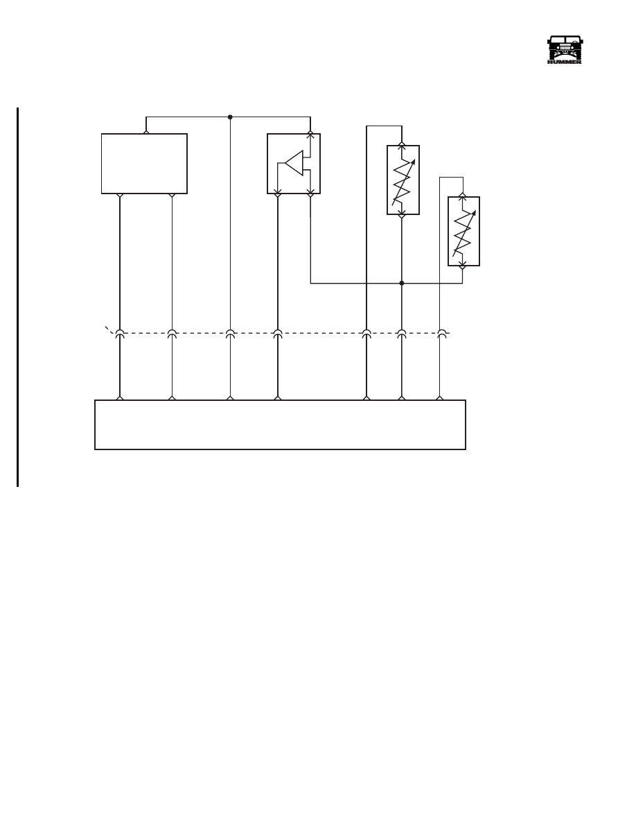
DTC P0237 Turbocharger (TC) Boost Sensor
Circuit Low Voltage
Circuit Description
The PCM sends a 5 volt reference signal to the boost sensor.
As manifold pressure changes, the electrical resistance of the
boost sensor also changes. By monitoring the sensor output
voltage, the PCM detects how much pressure is being pro-
duced by the turbocharger in the intake manifold. The PCM
uses the boost sensor to control turbo boost and fuel at different
loads. This is a type B DTC.
Conditions for Setting the DTC
• Boost pressure less than 40 kPa.
• Conditions met for 2 seconds.
Action Taken When the DTC Sets
No turbo boost.
Conditions for Clearing the MIL/DTC
• The PCM will turn the MIL off after three consecutive
trips without a fault condition.
• A History DTC will clear when forty consecutive
warm-up cycles that the diagnostic does not fail (coolant
temperature has risen 5°C (40°F) from start up coolant
temperature and engine coolant temperature exceeds
71°C (160°F) that same ignition cycle).
• Use of a Scan Tool.
Diagnostic Aids
With the ignition “ON” and the engine stopped, boost pressure
is equal to atmospheric pressure. Comparison of this reading
with known good vehicle using the same sensor is a good way
to check accuracy of a “suspect” sensor. Readings should be
the same +.4 volt. Very little boost can be attained by revving
the engine in neutral. If the Boost sensor signal circuit is open
or shorted to ground, Boost solenoid will show a zero duty cy-
cle. A J–39200 can be used to measure (actual) signal voltage
at the PCM harness connector.
Test Description
Number(s) below refer to the number(s) on the diagnostic table.
2. This step will determine if DTC P0237 is the result of a hard
failure or an intermittent condition.
3. This step simulates conditions for a DTC P0237. If the PCM
recognizes the change, the PCM and signal circuit are OK.
5 VOLT
REFERNCE
CKP
SENSOR
SIGNAL
SENSOR
GROUND
CRANK
SHAFT
POSITION
SENSOR
(CKP)
A
B
B
A
B
B
A
A
C
C
C5
BOOST/
BARO
PRESSURE
SENSOR
INTAKE AIR
TEMPERATURE
SENSOR (IAT)
ENGINE
COOLANT
TEMP
SENSOR
(ECT)
POWERTRAIN
CONTROL
MODULE
CKP
SENSOR
SIGNAL
SENSOR
GROUND
5 VOLT
REFERENCE
BOOST
SENSOR
SIGNAL
SENSOR
GROUND
IAT
SENSOR
SIGNAL
ECT
SENSOR
SIGNAL
C29-A5
651 BK
C29-B12
C27-D13
C27-C14
C27-C1
349 YL
359 BK
350 GY
394 LG
651 PP
354 YL
357 TN
9-S12-066
B9
B11
B12
B10
B5
C4
C5
C27-C11
C27-C4
359 PP
651 BK
4-1-00

_____________________________________________________
PCM/Tech 1 Scan Tool 71
®
05745159
DTC P0237 - Turbocharger (TC) Boost Sensor Circuit Low Voltage
Step
Action
Value(s)
Yes
No
1
Important:
Before clearing DTC(s) use the scan tool “Capture Info” to
record freeze frame and failure records for reference, as data will be lost
when “Clear Info” function is used.
Was the
“On-Board Diagnostic (OBD) System Check”
performed?
—
Go to Step 2.
Go to
OBD
System Check.
2
1. Scan tool connected.
2. Engine idling.
3. With J–39200 connected to ground, probe PCM harness connector Boost
signal circuit.
Does the J–39200 display a voltage less than the specified value?
1.0v
(40 kPa)
Go to Step 3. Go to Step 5.
3
1. Turn the ignition “OFF”.
2. Disconnect the Boost sensor electrical connector.
3. Jumper the Boost sensor 5 volt reference to the Boost sensor signal cir-
cuit at the harness.
4. Turn the ignition “ON”.
Does the scan tool display a Pressure greater than specified value?
202 kPa
Go to Step 6.
Go to Step 4.
4
1. Turn the ignition “OFF”.
2. Boost sensor still disconnected.
3. Remove the jumper wire.
4. Jumper the Boost sensor signal circuit at the harness with a test light con-
nected to B+.
5. Turn the ignition “ON”.
Does the scan tool display a Pressure greater than specified value?
202 kPa
(4.0v)
Go to Step 8.
Go to Step 7.
5
DTC is intermittent.
Are additional DTCs stored?
—
Go to DTC
table.
See Diagnostic
Aids
6
Check for a faulty connection at the Boost sensor.
Was a problem found?
—
Go to Step 13. Go to Step 10.
7
Check for an open or short to ground in Boost sensor signal circuit.
Was a problem found?
—
Go to Step 13. Go to Step 11.
8
Check for an open in the Boost sensor 5 volt reference circuit.
Was a problem found?
—
Go to Step 13.
Go to Step 9.
9
Check for a short to ground in Boost sensor 5 volt reference circuit.
Was a problem found?
—
Go to Step 13. Go to Step 12.
10
Replace the faulty Boost sensor.
Is the action complete?
—
Go to Step 13.
—
11
Check the terminal connectors at the PCM for a poor connections and repair
if necessary. Was a problem found?
—
Go to Step 13. Go to Step 12.
12
Replace the faulty PCM.
Notice:
If the PCM is faulty, the new PCM must
be programmed. Go to
PCM replacement and programming procedures.
Is the action complete?
—
Go to Step 13.
—
13
1. Using the Scan Tool, select “DTC”, “Clear Info”.
2. Start engine and idle at normal operating temperature.
3. Select “DTC”, “Specific”, then enter the DTC number which was set.
4. Operate vehicle within the conditions for setting this DTC as specified in
the supporting text.
Does the Scan Tool indicate that this diagnostic Ran and Passed?
—
Go to Step 14.
Go to Step 2.
14
Using the Scan Tool, select “Capture Info”, “Review Info”.
Are any DTCs displayed that have not been diagnosed?
—
Go to the
DTC table
System OK.

72
PCM/Tech 1 Scan Tool
_____________________________________________________
®
DTC P0238 Turbocharger (TC) Boost Sensor
Circuit High Voltage
Circuit Description
The PCM sends a 5 volt reference signal to the boost sensor.
As manifold pressure changes, the electrical resistance of the
boost sensor also changes. By monitoring the sensor output
voltage, the PCM detects how much pressure is being pro-
duced by the turbocharger in the intake manifold. The PCM
uses the boost sensor to control turbo boost and fuel at different
loads. This is a type B DTC.
Conditions for Setting the DTC
• Boost Pressure greater than or equal to 4.8 volts
(202 kPa).
• Engine Speed less than 3506 RPM.
Action Taken When the DTC Sets
No turbo boost.
Conditions for Clearing the MIL/DTC
• The PCM will turn the MIL off after three consecutive
trips without a fault condition.
• A History DTC will clear when forty consecutive
warm-up cycles that the diagnostic does not fail (coolant
temperature has risen 5°C (40°F) from start up coolant
temperature and engine coolant temperature exceeds
71°C (160°F) that same ignition cycle).
• Use of a Scan Tool.
Diagnostic Aids
With the ignition “ON” and the engine stopped, boost pressure
is approximately equal to Baro. Comparison of this reading
with known good vehicle using the same sensor is a good way
to check accuracy of a “suspect” sensor. Readings should be
the same +.4 volt. Very little boost can be attained by revving
the engine in neutral. A J–39200 can be used to measure (ac-
tual) signal voltage at the PCM harness connector.
Test Description
Number(s) below refer to the number(s) on the diagnostic table.
2. This step simulates conditions for a DTC P0237. If the PCM
recognizes the change, the PCM and the signal circuit are
OK.
3. This step will make sure the PCM is responding to a low
signal voltage. This will indicate that the PCM is OK.
5 VOLT
REFERNCE
CKP
SENSOR
SIGNAL
SENSOR
GROUND
CRANK
SHAFT
POSITION
SENSOR
(CKP)
A
B
B
A
B
B
A
A
C
C
C5
BOOST/
BARO
PRESSURE
SENSOR
INTAKE AIR
TEMPERATURE
SENSOR (IAT)
ENGINE
COOLANT
TEMP
SENSOR
(ECT)
POWERTRAIN
CONTROL
MODULE
CKP
SENSOR
SIGNAL
SENSOR
GROUND
5 VOLT
REFERENCE
BOOST
SENSOR
SIGNAL
SENSOR
GROUND
IAT
SENSOR
SIGNAL
ECT
SENSOR
SIGNAL
C29-A5
651 BK
C29-B12
C27-D13
C27-C14
C27-C1
349 YL
359 BK
350 GY
394 LG
651 PP
354 YL
357 TN
9-S12-066
B9
B11
B12
B10
B5
C4
C5
C27-C11
C27-C4
359 PP
651 BK
4-01-00
Нет комментариевНе стесняйтесь поделиться с нами вашим ценным мнением.
Текст