Hummer H1 (2002+). Manual — part 233

_____________________________________________________
Electrical System 12-153
®
05745159
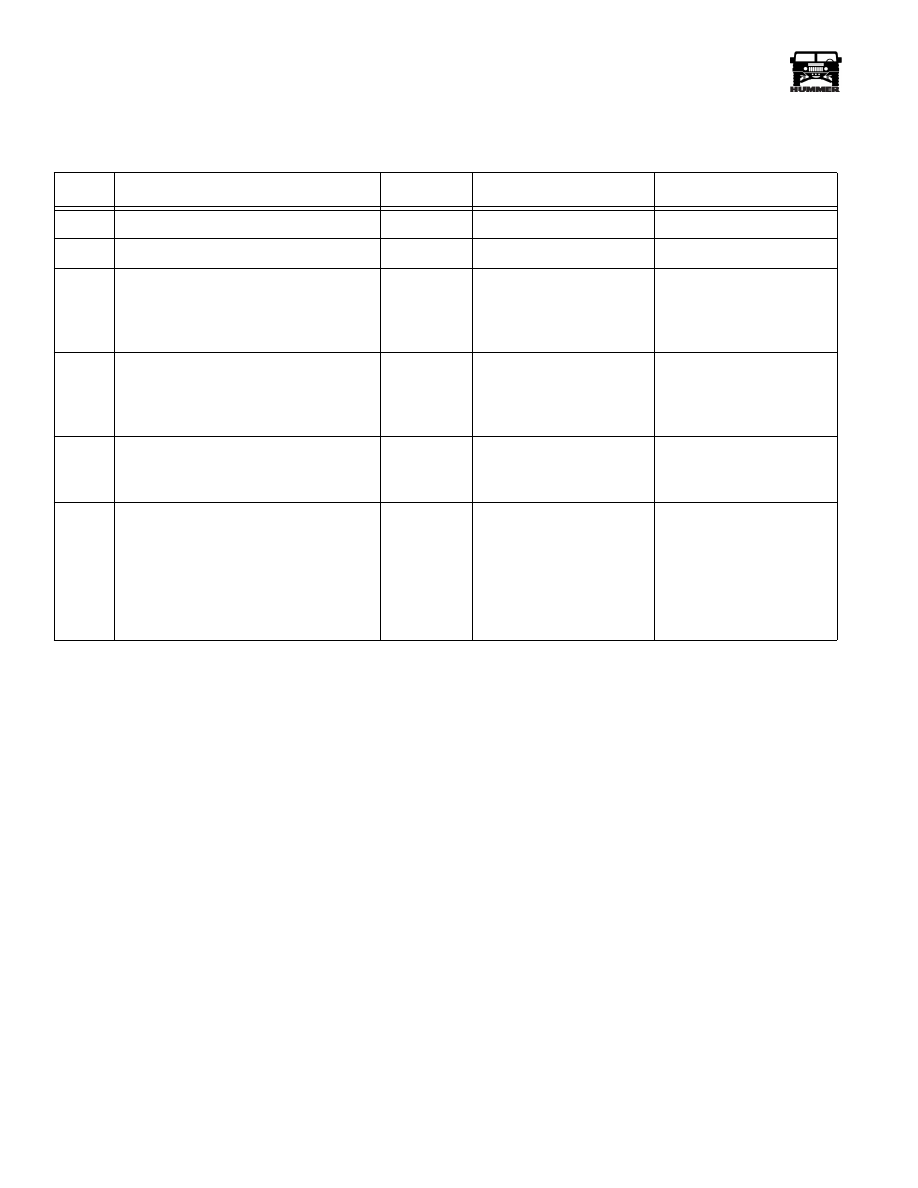
NO SOUND FROM ONE SPEAKER (DELCO MONSOON)
CHART #3
STEP
ACTION
VALUE(S)
YES
NO
1
Turn ignition switch to the “Run” position.
Turn radio “On”.
Insert cassette or compact disc from
Delco Audio system Diagnostic Kit
J–39916-A.
Set radio balance and fade controls to the
detente (center) position.
Set volume at normal listening level.
While playing the combination test tone
from cassette or compact disc, use a
DVOM to backprobe the speaker connec-
tor between terminals “A” and “B”.
Is the voltage greater than 0v AC?
> 0v AC
Go to step 2.
Go to step 3.
2
Check for a poor connection at the inop-
erative speaker.
If OK, replace the speaker.
Is the repair complete?
System OK.
3
Check the + and - speaker circuits for a
short to B+ or ground between the
speaker and amplifier.
Is there a short?
Repair short to ground or
B+.
Go to step 4.
4
Turn the ignition switch to the “Off” position.
Disconnect connector C62.
Using a DVOM set to measure resis-
tance, probe the amplifier connector
between the + and - speaker circuits of
the inoperative speaker (see schematics).
Is the resistance approximately 2-4
ohms?
2-4 ohms
Go to step 6.
Go to step 5.
5
Using a DVOM, check the resistance at
the speaker connection between termi-
nals “A” and “B”.
Is the resistance 2-4 ohms?
2-4 ohms
Repair open in speaker +
or - circuit between
speaker connection and
amplifier connection.
Replace the speaker.
6
Check for poor connection at connector
C62.
Is connection OK?
Replace amplifier.
Repair connection.
3-1-01

12-154
Electrical System
______________________________________________________
®
NO SOUND FROM ANY SPEAKER, RADIO DISPLAY OPERATES NORMALLY (DELCO MONSOON)
CHART #4
STEP
ACTION
VALUE(S)
YES
NO
1
Disconnect connector C62.
Turn ignition switch to the “Run” position.
Turn radio “On”.
Insert the cassette or compact disc from Delco
Audio System Diagnostic Kit J–39916-A.
Set radio balance and fade controls to the
detente (center) position.
Set radio volume at normal listening level.
While playing the combination test tone
from the cassette or compact disc, use a
DVOM to measure AC voltage between
connector C62 terminals “E6” and “E7”.
Is the voltage greater than 0v AC?
> 0v AC
Go to step 2.
Go to step 4.
2
Check for a poor connection at the connec-
tor C62 terminals “E6” and “E7”.
Was a poor connection found?
Repair connection.
Go to step 3.
3
Using a DVOM, check for +12v between
the light green wire and the black wire (ckts
829 and 59) at the amplifier connection.
+12v
Replace amplifier.
Repair open or poor con-
nection in ckts 829 and 59.
4
Turn the ignition switch to the “Run” position.
Turn the radio to the “On” position.
Insert the cassette or compact disc from Delco
Audio System Diagnostic Kit J–39916-A.
Set radio balance and fade controls to the
detente (center) position.
Set radio volume at normal listening level.
While playing the combination test tone
from the cassette or compact disc, use a
DVOM and backprobe connector C56
between terminals “16” and “15”.
Is the voltage greater than 0v AC?
> 0v AC
Repair the open or short
in ckts 821 or 820
between radio and
amplifier.
Go to step 5.
5
Check for a bad connection at connector
C56 terminals “16” or “15”.
Is bad connection found?
Repair connection.
Replace radio.
3-1-01

_____________________________________________________
Electrical System 12-155
®
05745159
COMPACT DISC CHANGER DOES NOT OPERATE PROPERLY
NOTE: Steps 1-4 cover the CD changer having no function with the radio operating normally
NOTE: Step 5 is used to diagnose a skipping or muted complaint.
NOTE: Step 6 is used if the display reads “FOCUS” or the disc ejected.
CHART #5
STEP
ACTION
VALUE(S)
YES
NO
1
Disconnect connector C61.
Turn ignition switch to the “Run” position.
Turn the radio “On”.
Select “CD mode” on radio display.
Using a DVOM, check for voltage on con-
nector C61 between terminals 13 and 15.
Is the minimum voltage present?
+12v
Go to step 3.
Go to step 2.
2
Back probe connector C58 between ter-
minals 18 and 15.
Is the minimum voltage present?
+12v
Repair power and/or
ground circuits between
radio and CD changer.
System OK.
Check for a poor connec-
tion at the radio.
If OK, service radio.
3
Using a DVOM, check for voltage on
connector C61 terminal 14.
Is the minimum voltage present?
+12v
Check for a poor connec-
tion at the CD changer.
If OK, service CD changer.
Go to step 4.
4
Back probe connector C58 and check the
voltage.
Is the minimum voltage present?
+12v
Repair the power control
circuit between the radio
and the CD changer.
Check for a poor connec-
tion at the radio.
If OK, service radio.
5
Check disc for proper insertion, scratches,
dirt or finger prints and clean if necessary.
Is usual route over a rough road (off road envi-
ronment)? If so, condition may be normal.
Attempt to duplicate on good road surface.
Test with known good disc (preferably new
disc). Some discs may contain marks not
readily visible that may make one track or
the entire disc unplayable.
Check mounting angle adjustment on
both sides of changer.
Is angle adjusted to 45 degrees?
If checks and adjustments do not cure
problem, service changer.
45 degrees
Service changer.
Loosen screws and adjust
mount angle to 45 degrees.
6
“FOCUS” appears if disc is inserted upside
down, dirty, badly scratched or wet.
“FOCUS” appears if moisture condenses
on the disc (if a cold disc is inserted into a
hot player and vice versa). Allow up to an
hour to evaporate condensation. Check with
known good disc - verify to customer. Very
high internal instrument panel temperatures
may cause eject.
If checks and adjustments do not cure
problem, service changer.
3-1-01
12-156
Electrical System
______________________________________________________
®
CASSETTE PLAYER DOES NOT OPERATE PROPERLY
CHART #6
STEP
ACTION
VALUE(S)
YES
NO
Tape plays weak, slow or garbled.
Go to step 1.
Tape inoperative.
Go to step 3.
1
Inspect and clean moving parts and tape
head or use Delco Audio System Diag-
nostic Kit J– 39916-A cleaning cassette.
Does tape play OK?
Advise periodic cleaning.
Go to step 2.
2
Perform motor speed test with diagnostic
test tape from Delco Audio System Diag-
nostic Kit J–39916-A.
Is motor speed OK?
Fault is in tape.
System OK.
Service radio.
3
Check player for obstruction through
tape door.
Is there an obstruction?
Go to step 4.
Service radio.
4
Remove obstruction. CAUTION:
improper removal may damage tape
player.
Inspect and clean moving parts and tape
head or use cleaning cassette.
Use diagnostic test tape from J–39916-A.
Does test tape operate?
System OK.
Service radio.
3-1-01
Нет комментариевНе стесняйтесь поделиться с нами вашим ценным мнением.
Текст