Hummer H1 (2002+). Manual — part 232
_____________________________________________________
Electrical System 12-149
®
05745159
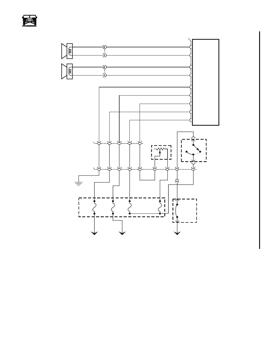
Figure 12-148: Standard Audio Harness Schematic Model 89.
BK
RD
B
A
LF SPEAKER
BK
RD
B
A
RF SPEAKER
8
7
6
4
3
RADIO
IGNITION
BATT 12V
DIMMER
ILLUMINATION
GROUND
11
12
13
14
LF
LF
RF
RF
C56
00-S12-040
–
+
–
+
4
Ω
4
Ω
813 BK
804 TN
811 BK
805 TN
17 PP
14 LB
137 RD
476 GY
59 BK
C3
PANEL
LIGHT
DIMMER
476 GY
59 BK
FUSE
1F
5 AMP
J6
C1
B4
G3
F3
C60
C
B
A
E
D
FUSE
4G
7.5 AMP
FUSE
2H
10 AMP
H9
K7
FUSE
2F
5 AMP
EXTERNAL
FUSE BOX
137 RD
14 LB
19 YL
H6
B1
37 RD
297 OR
TO BATTERY
TO BATTERY
TO IGNITION
14 LB
17 PP
38 RD
C1-67
HEADLIGHT
SWITCH
G4
OFF
HEAD
PARK
2
1
INTERNAL
FUSE BOX
CIRCUIT
BREAKER
#2
30 AMP
3-1-01
12-150
Electrical System
______________________________________________________
®
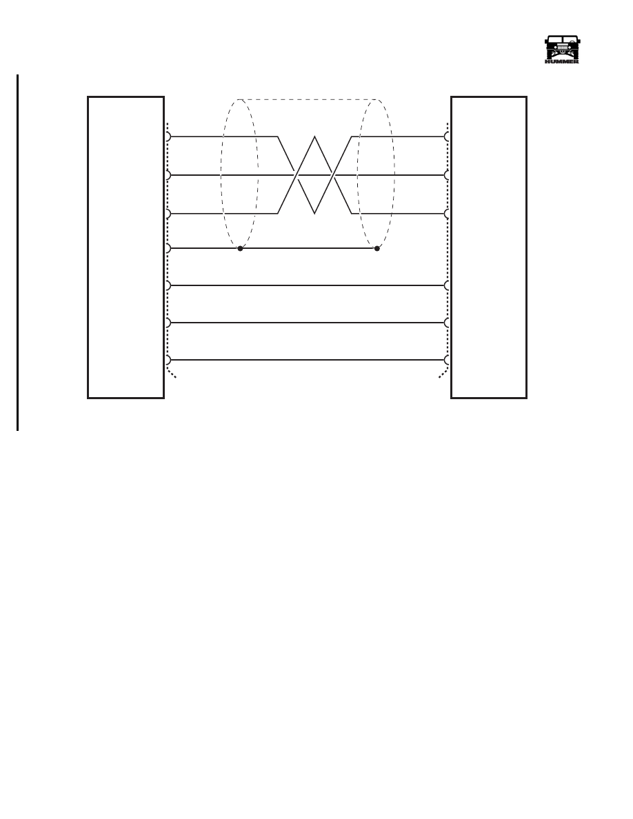
Figure 12-149: CD Changer To Radio Harness, All Models.
13
11
CD CHANGER
RADIO
16
10
19
12
SHIELD
9
15
15
18
13
C61
14
14
RIGHT
AUDIO
SIGNAL
LEFT
AUDIO
SIGNAL
AUDIO COMMON
DRAIN
GROUND
DATA
BATT
00-S12-002
YL
WT
GY
RD
BK
PP
LEFT
AUDIO
SIGNAL
RIGHT
AUDIO
SIGNAL
AUDIO COMMON
BATT
GROUND
DATA
C58
3-1-01
_____________________________________________________
Electrical System 12-151
®
05745159
SYMPTOM TABLE
SYMPTOM
PROCEDURE
PAGE NUMBER
Display inoperative, no sound from any
speaker.
Chart #1
12-152
No sound from one speaker (Delco
std.).
Chart #2
12-152
No sound from one speaker (Monsoon).
Chart #3
12-153
No sound from any speaker, radio dis-
play operates normally (Monsoon).
Chart #4
12-154
Compact disc player does not operate
properly.
Chart #5
12-155
Cassette player does not operate prop-
erly.
Chart #6
12-156
Antenna system test.
Chart #7
12-157
Rear seat audio does not operate.
Chart #8
12-160
Radio controls are inoperative.
Service radio.
Radio does not turn off.
Service radio.
Radio memory (clock and station pre-
sets) is inoperative.
Check the gray wire (CKT 476) for an
open or high resistance between C56
terminal 7 and fuse 2H of the interior
fuse box.
Display dimming does not vary using
the I/P dimmer switch (I/P dimming
works).
Check the purple wire (CKT 17) for an
open or high resistance between C56
terminal “6” and the panel light dimmer.
Speaker output distorted at high volume
(Monsoon).
Check for open or poor connection in the
black wire (CKT 59) from C62 terminals
“E8” and “E9” to the ground G4. Check
for open or poor connection in the light
green wire (CTK 829) from C62 terminals
“E11” and “E12” to fuse 1D.
If OK, replace amplifier.
3-1-01
12-152
Electrical System
______________________________________________________
®
DISPLAY IS INOPERATIVE, NO SOUND FROM ANY SPEAKER
NO SOUND FROM ONE SPEAKER (DELCO STANDARD)
CHART #1
STEP
ACTION
VALUE(S)
YES
NO
1
Disconnect connector C56.
Turn the ignition switch to the “Run”
position.
With a DVOM, measure voltage between
terminal “7” and ground G4.
+12v
Go to step 2.
Repair the poor connection
or open the gray wire (CKT
476) between connector C56
terminal “7” and fuse 2H of
the interior fuse box.
2
With a DVOM, measure the voltage at
connector C56 between terminal “7” and
terminal “8”.
+12v
Go to step 3.
Repair the poor connec-
tion or open in the black
wire (CKT 59) between
connector C56 terminal
“8” and ground G4.
3
With a DVOM measure the voltage at
connector C56 between terminal “4” and
terminal “8”.
+12v
Go to step 4.
Repair open in the red wire
(CKT 137) between connec-
tor C56 terminal 4 and fuse
4G of the interior fuse box.
4
Check for a poor connection at the radio.
If OK, service radio.
CHART #2
ACTION
VALUE(S)
YES
NO
1
Turn the ignition switch to the “off” position.
Disconnect connectors C56, C57 and C58.
With a DVOM, measure the resistance at
the connector C56 between speaker +
and - circuits (see schematics).
4
Ω
Go to step 3.
Go to step 2.
2
With a DVOM, measure the resistance at
the speaker connection from terminal
“A” to terminal “B”.
4
Ω
Repair open or short circuit
in speaker + and - circuits.
Replace speaker.
3
With a DVOM measure the resistance at
the radio connector of the speaker + and -
circuits to ground.
Infinite
resistance.
Go to step 4.
Repair short to ground in
speaker + or - circuit.
4
Check for poor connections at radio or
speaker.
If OK, service radio.
3-1-01
Нет комментариевНе стесняйтесь поделиться с нами вашим ценным мнением.
Текст