Hummer H1 (2002+). Manual — part 209

______________________________________________________
Electrical System 12-63
®
05745159
Figure 2-82: Horn Schematic
HORN RELAY
EXTERIOR
FUSE BOX
HORN
HORN
FUSE
1D
20 AMP
EXTERIOR
FUSE
BOX
460 BK
1 DB
C1-62
7 RD
6 WH
G4
G2
58 BK
HORN
SWITCH
00-S12-007
ADAPTER
ADAPTER
C39-C
TO
REMOTE
ENTRY
MODULE
TO
BATT
7 RD
1F
1E
3F
3E
4-1-00
12-64
Electrical System
_______________________________________________________
®
INSTRUMENT PANEL, GAUGES, AND
SWITCHES
Instrument Panel (I.P.) Replacement
Removal
NOTE: Tag all leads prior to removal for installation. If re-
placing instrument panel, refer to procedures in this section to
remove and/or disconnect the various lamps, switches, and
gauges.
1.
Disconnect negative battery cables (Section 12).
2.
Remove left side crashpad.
3.
Remove close-out panel.
4.
Remove wiring harness close-out plate.
5.
Remove tachometer and clock assembly from I.P. to
access right side I.P. mounting bolt.
6.
Remove right side I.P. mounting bolt.
7.
Remove two bolts securing I.P. to steering column.
8.
Remove two left side I.P. mounting bolts securing I.P. to
A-pillar.
9.
Disconnect air hose from side window defrost vent.
10. Remove I.P.
Installation
1.
Maneuver I.P. into position between steering wheel and
firewall.
2.
Connect air hose side window defrost vent.
3.
Loosely install left side I.P. mounting bolts.
4.
Loosely install I.P. to steering column mounting bolts.
5.
Install right side I.P. mounting bolts
6.
Tighten loosely installed bolts from steps 3 and 4.
7.
Install tachometer and clock assembly.
8.
Install wiring harness close-out plate.
9.
Install close-out panel.
10. Install left side dashpad.
11. Connect negative battery cables (Section 12).
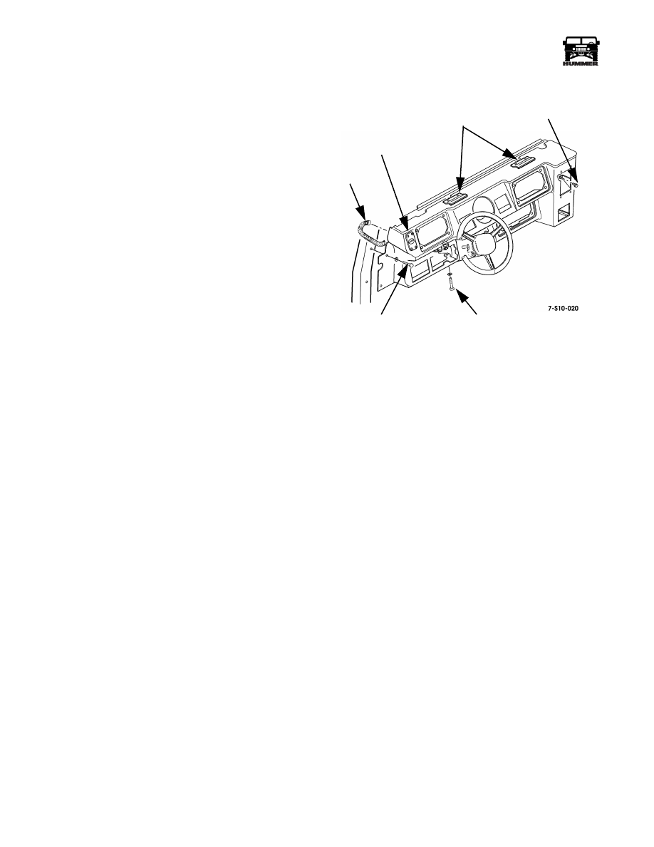
Figure 2-83: Instrument Panel Replacement
AIR
HOSE
SIDE WINDOW
DEFROST VENT
RIGHT SIDE
MOUNTING BOLT
STEERING COLUMN
MOUNTING BOLTS
LEFT SIDE
MOUNTING BOLTS
I. P. CLIPS
4-1-00
______________________________________________________
Electrical System 12-65
®
05745159
Crashpad Replacement (Right Side)
Removal
1.
Remove screw/washers, and crashpad from dashboard
(Figure 2-84).
2.
Disconnect air hose from vent duct.
3.
Remove screws, side window vent, and vent duct from
crashpad.
Installation
1.
Secure vent duct and window vent to crashpad with screws
(Figure 2-84).
2.
Connect air hose to vent duct.
3.
Secure crashpad to dashboard with screw/washers.
Figure 2-84: Crashpad Replacement
Crashpad Replacement (Left Side)
Removal
1.
Remove screw/washers from top of crashpad.
2.
Tug gently on crashpad toward steering wheel to free
crashpad clips from I. P. clips (Figures 2-83 and 2-84).
3.
Lift vent side of crashpad and work console side (duct
nozzle) out of front console.
Installation
1.
Work console side (duct nozzle) of crashpad into front
console plenum.
2.
Position crashpad on edge of I. P. closest to steering wheel
and push crashpad onto I. P. clips (Figures 2-83 and 2-84).
3.
Secure crashpad to I. P. with screw/washers.
Gauge Replacement
NOTE: Gauge replacement is basically the same for all instru-
ment panel gauges.
Removal
1.
Remove screws and pull gauge panel away from instru-
ment panel (Figure 2-85).
2.
Disconnect lamp connector from gauge.
NOTE: Tag all leads prior to removal for installation.
3.
Remove nut and lockwasher assemblies securing three
leads to gauge.
4.
Remove hold-down bracket.
5.
Remove gauge through front of gauge panel.
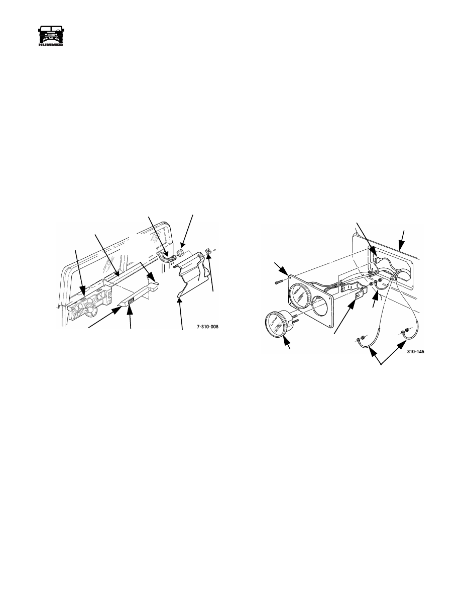
Figure 2-85: Gauge Replacement
Installation
1.
Insert gauge through front of gauge panel (Figure 2-85).
2.
Secure hold-down bracket and lead to gauge with nut and
lockwasher assembly.
3.
Secure leads to gauge with nut and lockwasher assemblies.
4.
Connect lamp connector to back of gauge.
5.
Start engine and ensure gauge operates properly.
6.
Secure gauge panel to instrument panel with screws.
DASHBOARD
AIR HOSE
VENT
DUCT
WINDOW
VENT
CRASH PAD
(RIGHT SIDE)
CRASH PAD
(LEFT SIDE)
VENT
DUCT
CONSOLE
NOZZLE/
SIDE
I. P. CLIPS
LAMP
INSTRUMENT
LEADS
HOLD-DOWN
LEAD
GAUGE
GAUGE PANEL
PANEL
CONNECTOR
BRACKET
4-1-00

12-66
Electrical System
_______________________________________________________
®
Instrument Panel Indicator Lamp
Replacement
NOTE: All instrument panel indicator lamps are replaced basi-
cally the same.
Removal
1.
Remove instrument panel.
2.
Turn lamp socket one-quarter turn counterclockwise, and
remove socket from indicator light housing.
3.
Pull lamp from socket (Figure 2-86).
Installation
1.
Push lamp into socket (Figure 2-86).
2.
Insert socket into status center and secure by turning
socket clockwise one-quarter turn.
3.
Install instrument panel.
4.
Start engine and ensure lamp operates properly.
Figure 2-86: Instrument Panel Indicator Light
Replacement
Instrument Panel Switch Replacement
NOTE: All instrument panel switches are replaced similarly,
with the exception of the dimmer control switch. This proce-
dure covers the main light switch.
CAUTION: Some connectors can be installed incorrectly and
cause damage to the electrical system. Make note of connector
position prior to removal.
Removal
1.
Remove closeout panel.
2.
Reach up behind IP and push switch from switch housing.
3.
Remove connector from switch (Figure 2-87).
Installation
1.
Install connector on switch (Figure 2-87).
2.
Install switch in switch housing.
3.
Install closeout panel.
Figure 2-87: Instrument Panel Switch Replacement
Instrument Panel Dimmer Control Switch
Replacement
Removal
1.
Remove closeout panel.
2.
Reach up behind instrument panel and push switch from
switch housing.
3.
Unplug connector from wiring harness (Figure 2-88).
Figure 2-88: Instrument Panel Dimmer Control
Switch Replacement
Installation
1.
Plug connector into wiring harness.
2.
Install switch in switch housing (Figure 2-88).
3.
Install closeout panel.
9-S06-015.1
BULB SOCKET
STATUS CENTER
SWITCH
HOUSING
INSTRUMENT PANEL
CONNECTOR
WIRING HARNESS
CONNECTOR
SWITCH
INSTRUMENT PANEL
HOUSING
4-1-00
Нет комментариевНе стесняйтесь поделиться с нами вашим ценным мнением.
Текст