Hummer H1 (2002+). Manual — part 197

______________________________________________________
Electrical System 12-15
®
05745159
Figure 12-26: Load Test Values vs.Temperature
5.
If voltage drops below the minimum value listed, replace
the battery.
Parasitic Draw Test
Tools Required:
• J–38758 Parasitic Draw Test Switch
• J–39200 Digital Multimeter
1.
Remove the negative battery cable from the rear battery.
2.
Install the male end of the parasitic draw test switch over
the crossover negative battery cable using the long battery
bolt from the battery cable removed in step 1.
3.
Open the parasitic draw test switch
4.
Connect the negative battery cable to female end of the
parsitic draw test switch using a short battery bolt.
5.
Close the parsitic draw test switch.
6.
Road test the vehicle while activating all accessories, such
as the radio and air conditioning.
7.
Turn the ignition switch to the off position and remove the key.
NOTE: It is important that from this point on, electrical conti-
nuity must be maintained in the ground circuit to the battery,
either through J–38758 in the on position, or through J–39200.
8.
Some components, such as the PCM or TCM, have timers
that draw several amps of current while they cycle down.
This can give a false parasitic drain reading. Wait 15
minutes for these components to power down before
continuing this test.
NOTE: If another DVOM is being used other than J–39200,
ensure that the ammeter will handle 10 amps of current without
damage.
9.
Install a jumper wire with a 10 amp fuse between the two
terminals on the parasitic draw test switch. Open the
switch and wait 10 seconds. If the fuse does not blow, the
parasitic load is less than 10 amps and the J–39200 can be
used. Close the switch on the tester and remove the jumper
wire and fuse.
10. Set J–39200 to the 10 amp scale and place leads in the
correct ports in the meter for amperage testing on the 10
amp scale.
11. Connect the meter leads to the two terminals on the
parasitic load test switch and open the switch.
12. Wait 60 seconds then take a reading from the meter. If the
current reading is at or below 2 amps, turn the test switch
to the on position. Reset the meter to read milliamps.
13. Open the switch and take the reading in milliamps.
14. Find the reserve capacity of the batteries on the vehicle.
Since there are 2 batteries, add the reserve capacities
together. (100 minutes + 100 minutes = 200 minutes
reserve capacity). Divide the number by 4 and the answer,
given in milliamps, is the maximum allowable parasitic
drain the batteries will support.
NOTE: Always turn the switch knob to the “on” position be-
fore removing each fuse to maintain continuity in the electrical
system and to avoid damaging the meter due to accidental
overloading, such as opening a door to change a fuse.
15. If current draw is too high, remove system fuses one at a
time until the draw returns to a value less than or equal to
the maximum allowable for the batteries. Repeat the test
for parasitic drain after any repair has been performed.
16. When the cause of excessive current draw has been
located and repaired, remove the meter, test switch and
terminal adapters and connect the negative battery cable to
the battery.
Estimated Temperature
Minimum Voltage
70°F(21°C)
9.6
50°F(10°C)
9.4
30°F(0°C)
9.1
15°F(-10°C)
8.8
0°F(-18°C)
8.5
0°F(Below -18°C)
8.0
4-1-00
12-16
Electrical System
_______________________________________________________
®
BATTERY CABLE REPLACEMENT
Battery Negative Cables - Removal
1.
Remove caps from battery negative cable (Figure 12-27).
2.
Remove battery cable bolts.
3.
Disconnect winch negative cable, if equipped (Figure 12-27).
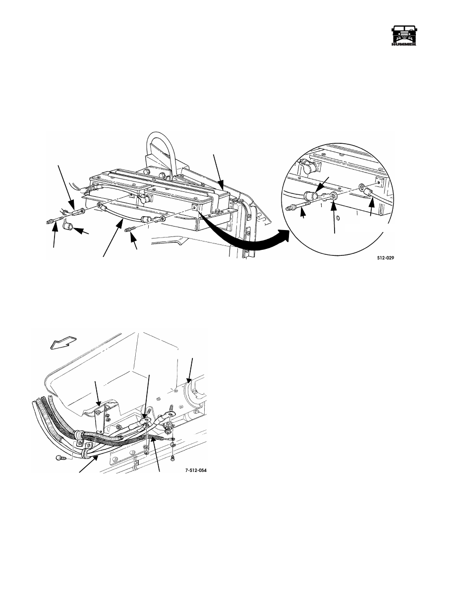
Figure 12-27: Battery Negative Cable Connections
4.
Remove fasteners securing negative cable to cable hanger
and starter then remove negative cable (Figure 12-28).
Figure 12-28: Negative Cable to Cylinder Block
Attachment
Battery Negative Cables - Installation
1.
Connect negative cables to starter, cable hanger, and bat-
teries.
2.
Tighten battery cable bolts to 8-12 lb-ft. (11-16 N•m).
3.
Install caps on battery cable bolts.
Battery Positive Cable - Removal
1.
Disconnect battery negative cables.
2.
Remove caps from battery positive cable(s) (Figure 12-29).
3.
Disconnect starter cable at battery.
4.
Disconnect battery positive cable, and winch cable, if
equipped, at battery.
5.
Remove locknut, washer, capscrew, and clamp securing
starter cable to bracket.
6.
Disconnect starter cable at starter.
NEGATIVE CABLE
CABLE BOLT
BOOT
BATTERY
CABLE
BOLT
BATTERY
CABLE
BOLT
NEGATIVE
BATTERY
CABLE
WITH WINCH ONLY
TO STARTER
NEGATIVE
CABLE
WINCH
NEGATIVE CABLE
CAP
ENGINE
NEGATIVE
HARNESS
BATTERY CABLE
STARTER
CABLE
HANGER
POSITIVE
BATTERY
CABLE
4-1-00
______________________________________________________
Electrical System 12-17
®
05745159
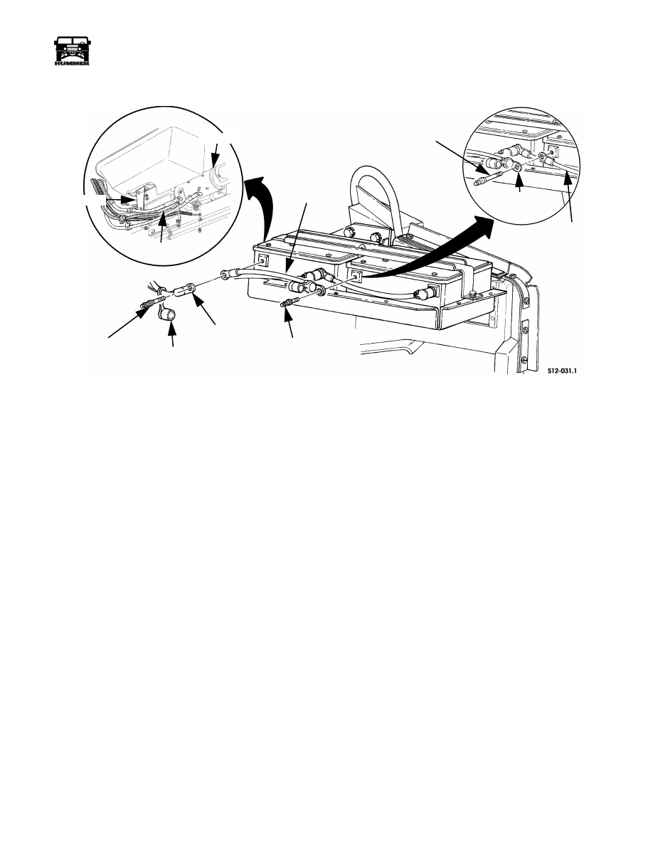
Figure 12-29: Battery Positive Cable Connections
Battery Positive Cables - Installation
1.
Connect starter cable to starter with lockers and nut.
Tighten nut to 12-16 lb-ft (16-22 N•m).
2.
Secure starter cable to bracket with clamp, capscrew,
washer, and locknut.
3.
Connect battery positive cable to battery.
4.
Connect winch cable to battery positive post
(Figure 12-29).
5.
Connect battery negative cables.
6.
Tighten cable-to-battery bolts to 8-12 lb-ft. (11-16 N•m).
BATTERY
CAP
BATTERY
POSITIVE
WINCH
BATTERY
STARTER CABLE
CABLE BOLT
WITH WINCH ONLY
BATTERY
BATTERY
POSITIVE CABLE
CABLE
POSITIVE CABLE
CABLE BOLT
STARTER
CABLE
STARTER
BRACKET
CABLE
BOLT
4-1-00
12-18
Electrical System
_______________________________________________________
®
BATTERY REPLACEMENT
WARNING: Battery electrolyte contains sulfuric acid
which can cause severe burns. If acid contacts eyes or
skin, flush affected areas liberally with water and ob-
tain medical assistance immediately. If acid contacts
clothing, flush with water and replace affected clothing.
Always wear eye protection, and remove all jewelry be-
fore working on batteries.
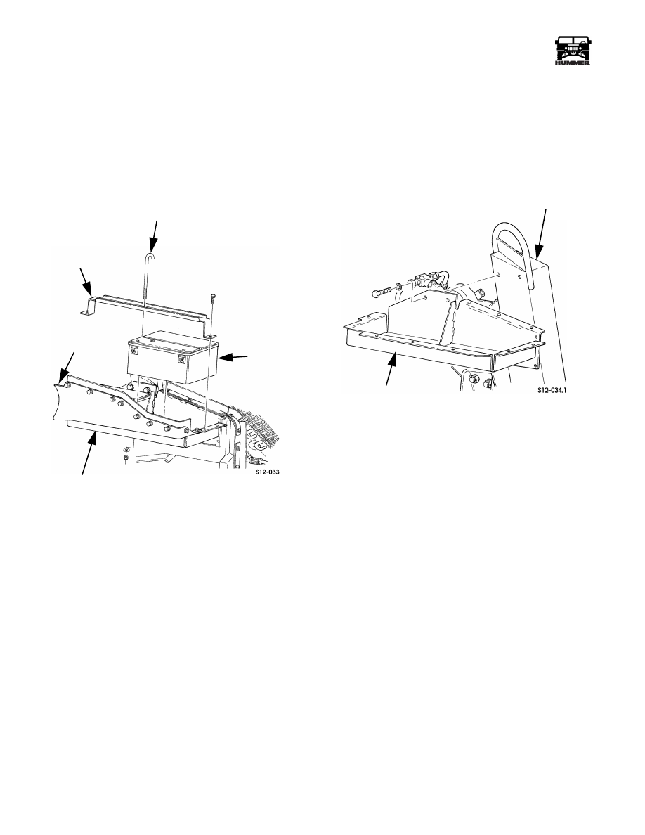
Figure 12-30: Battery Removal/Installation
1.
Disconnect battery cables.
2.
Remove J-hook, and holddown bracket bolts (Figure 12-30).
3.
Remove holddown bracket.
4.
Remove one or both batteries as required.
5.
Clean battery tray.
6.
Install one or both batteries in tray (Figure 12-30).
7.
Install holddown bracket and J-hook.
8.
Connect battery cables.
BATTERY TRAY REPLACEMENT/INSTALLATION
1.
Disconnect and remove batteries.
2.
Remove splash shield and battery tray shield.
3.
Remove battery tray from airlift bracket (Figure 12-31).
4.
Install battery tray on airlift bracket.
5.
Install battery tray shield and splash shields.
6.
Install and connect batteries.
Figure 12-31: Battery Tray
BATTERY
HOLDDOWN
BRACKET
SPLASH SHIELD
BATTERY TRAY
J-HOOK
BATTERY
BATTERY TRAY
AIRLIFT BRACKET
4-1-00
Нет комментариевНе стесняйтесь поделиться с нами вашим ценным мнением.
Текст