Hummer H1 (2002+). Manual — part 135
________________________________________________________________________________
9-1
®
05745159
Section 9 Axles, Suspension, and Frame
TABLE OF CONTENTS
Airlift Brackets . . . . . . . . . . . . . . . . . . . . . . . . . . . . . . . . . 9-48, 9-49
Axle
Output Shaft Seal Replacement . . . . . . . . . . . . . . . . . . . .9-25
Pinion Seal Replacement . . . . . . . . . . . . . . . . . . . . . . . . . .9-26
Support and Side Mounting Brackets . . . . . . . . . . . . . . . .9-59
Vent Line Replacement . . . . . . . . . . . . . . . . . . . . . . . . . . . .9-23
Cover Service . . . . . . . . . . . . . . . . . . . . . . . . . . . . . . . . . . . .9-25
Repair . . . . . . . . . . . . . . . . . . . . . . . . . . . . . . . . . . . . . . . . . .9-28
Replacement . . . . . . . . . . . . . . . . . . . . . . . . . . . . . . . . . . . .9-26
Front Bumper and Towing Brackets . . . . . . . . . . . . . . . . .9-45
Rear Bumper Outer Mounting and Tiedown Brackets . . .9-53
Rear Bumper Replacement . . . . . . . . . . . . . . . . . . . . . . . .9-52
Front Suspension Brace Replacement . . . . . . . . . . . . . . .9-50
Front Suspension Front Crossmember . . . . . . . . . . . . . . .9-60
Front Suspension Rear Crossmember . . . . . . . . . . . . . . .9-61
Inspection . . . . . . . . . . . . . . . . . . . . . . . . . . . . . . . . . . . . . . .9-64
Left Engine Mount Bracket . . . . . . . . . . . . . . . . . . . . . . . .9-54
Left Intermediate Body Mount Bracket . . . . . . . . . . . . . . .9-57
Lifting Shackle Replacement . . . . . . . . . . . . . . . . . . . . . . .9-47
Radiator Front Mount Bracket . . . . . . . . . . . . . . . . . . . . . .9-46
Rear Suspension Front Crossmember . . . . . . . . . . . . . . .9-62
Rear Suspension Rear Crossmember . . . . . . . . . . . . . . . .9-63
Rear-Front Tiedown Bracket. . . . . . . . . . . . . . . . . . . . . . . .9-59
Rear-Rear Tiedown Bracket . . . . . . . . . . . . . . . . . . . . . . . .9-58
Repairs . . . . . . . . . . . . . . . . . . . . . . . . . . . . . . . . . . . . . . . . .9-67
Right Engine Mount Bracket . . . . . . . . . . . . . . . . . . . . . . .9-55
Right Front Body Mount Bracket . . . . . . . . . . . . . . . . . . . .9-55
Right Intermediate Body Mount Bracket . . . . . . . . . . . . .9-57
Transmission Crossmember Support . . . . . . . . . . . . . . . .9-56
Input Seal Replacement . . . . . . . . . . . . . . . . . . . . . . . . . . . 9-11
Repair . . . . . . . . . . . . . . . . . . . . . . . . . . . . . . . . . . . . . . . . . . 9-12
Replacement . . . . . . . . . . . . . . . . . . . . . . . . . . . . . . . . . . . . . 9-8
Side Cover Replacement . . . . . . . . . . . . . . . . . . . . . . . . . . 9-11
Spindle Bearing Adjustment . . . . . . . . . . . . . . . . . . . . . . . 9-19
Spindle Seal Replacement . . . . . . . . . . . . . . . . . . . . . . . . . 9-17
Vent Line Replacement. . . . . . . . . . . . . . . . . . . . . . . . . . . . 9-24
Halfshaft Boot Replacement . . . . . . . . . . . . . . . . . . . . . . . . . . . 9-21
Splash Shield Support Bracket Replacement . . . . . . . . . . . . . 9-51
Spring Seat Replacement. . . . . . . . . . . . . . . . . . . . . . . . . . . . . . 9-53
Suspension System
Control Arm Bushing Replacement . . . . . . . . . . . . . . . . . . 9-7
Frame Extension Replacement . . . . . . . . . . . . . . . . . . . . . 9-47
Front Bumper and Towing Brackets . . . . . . . . . . . . . . . . . 9-45
Front Bumper Mounting Bracket . . . . . . . . . . . . . . . . . . . . 9-46
Lower Ball Joint Replacement . . . . . . . . . . . . . . . . . . . . . . . 9-5
Lower Control Arm Replacement . . . . . . . . . . . . . . . . . . . . 9-7
Radius Rod Replacement . . . . . . . . . . . . . . . . . . . . . . . . . . 9-3
Rear Upper Control Arm Bracket. . . . . . . . . . . . . . . . . . . . 9-58
Stabilizer Bar Link Replacement . . . . . . . . . . . . . . . . . . . . . 9-2
Stabilizer Bar Replacement . . . . . . . . . . . . . . . . . . . . . . . . . 9-2
Upper Ball Joint Replacement . . . . . . . . . . . . . . . . . . . . . . 9- 4
Upper Control Arm Replacement . . . . . . . . . . . . . . . . . . . . 9-5
Assembly Repair . . . . . . . . . . . . . . . . . . . . . . . . . . . . 9-72, 9-81
Cable Replacement . . . . . . . . . . . . . . . . . . . . . . . . . 9-71, 9-80
Electric Thermal Switch/Brush Assembly . . . . . . . 9-76, 9-85
Replacement . . . . . . . . . . . . . . . . . . . . . . . . . . . . . . . 9-70, 9-79
Troubleshooting . . . . . . . . . . . . . . . . . . . . . . . . . . . . . . . . . 9-70

9-2
Axles, Suspension, and Frame
___________________________________________
®
SUSPENSION SYSTEM DESCRIPTION
The HUMMER suspension system consists of a heavy-duty
coil spring, a heavy-duty hydraulic shock absorber, and an up-
per and lower control arm at each wheel. This suspension sys-
tem provides for a smoother ride and allows for more positive
control of the vehicle.
Ball joints allow the control arms and geared hubs to change
angles for smooth steering during turns. A stabilizer bar is lo-
cated on the front suspension to aid in stabilizing the vehicle
when it is turning. Each end of the stabilizer bar is attached to
the lower control arms (Figure 9-1).
Figure 9-1: Suspension System
STABILIZER BAR REPLACEMENT
Removal
NOTE:
Stabilizer bar must be removed from bar links at each
end of lower control arms.
1.
Remove two locknuts, three washers, and pin securing bar
link to stabilizer bar (Figure 9-2).
2.
Remove two locknuts, washers, clamp, and stabilizer bar
from frame bracket.
3.
Remove bushing from stabilizer bar.
Installation
1.
Install bushing on stabilizer bar (Figure 9-2).
2.
Install stabilizer bar on frame bracket with clamp, two
washers, and locknuts. Tighten locknuts to 60 lb-ft
(81 N•m).
3.
Install stabilizer bar on bar link with pin, three washers,
and two locknuts. Tighten locknuts to 75 lb-ft (102 N•m).
Figure 9-2: Stabilizer Bar Replacement
STABILIZER BAR LINK REPLACEMENT
Removal
1.
Remove locknut and two washers securing bar link to sta-
bilizer bar (Figure 9-3).
2.
Remove bolt, two washers, and bar link from lower
control arm.
Installation
1.
Apply thread-locking compound to threads of bolt. Install
bar link to lower control arm with two washers and bolt.
Tighten bolt to 70 lb-ft (95 N•m) (Figure 9-3).
2.
Install bar link on stabilizer bar with two washers and
locknut. Tighten locknut to 75 lb-ft (102 N•m).
Figure 9-3: Stabilizer Bar Link Replacement
UPPER
BALL
GEARED HUB
LOWER
SHOCK
COIL
CONTROL
JOINT
SPRING
ABSORBER
CONTROL
ARM
ARM
BUSHING
FRAME
BAR LINK
PIN
STABILIZER
BRACKET
BAR
BAR LINK
LOWER
STABILIZER
BAR
CONTROL ARM
__________________________________________
Axles, Suspension, and Frame 9-3
®
05745159
RADIUS ROD REPLACEMENT
Removal
1.
Remove wheel.
2.
Remove cotter pin, slotted nut, and washer securing radius
rod to geared hub (Figure 9-4).
3.
Using puller J–24319-B or equivalent, separate radius rod
from geared hub.
4.
Remove locknut, washers, bolt, and radius rod from
bracket.
Installation
1.
Install radius rod on bracket with washer, bolt, washer, and
locknut. Tighten locknut to 260 lb-ft (353 N•m)
(Figure 9-4).
CAUTION:
Do not loosen slotted nut to install cotter pin. Do-
ing this may result in damage to equipment.
NOTE:
When slotted nuts are tightened to prescribed torque
values, cotter pins must have a minimum of 50% engagement
with the nut slots.
2.
Install radius rod on geared hub with washer and slotted
nut. Tighten slotted nut to 70 lb-ft (95 N•m). Install cotter
pin in slotted nut.
3.
Install wheel.
Figure 9-4: Radius Rod Replacement
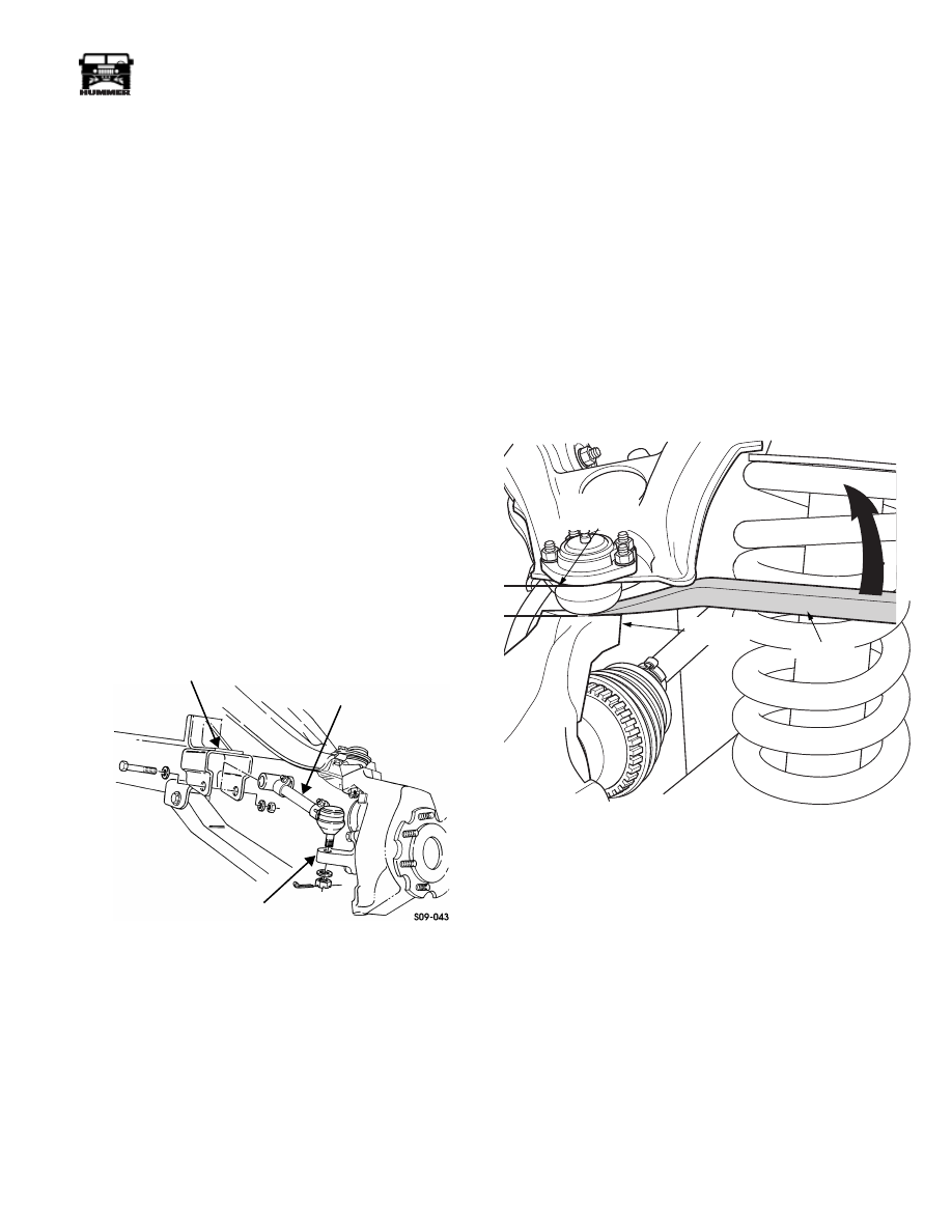
UPPER BALL JOINT WEAR CHECK PROCEDURE
NOTE:
If the vehicle was previously lifted off the ground for
other service, center the steering wheel, roll the vehicle for-
ward and back to settle the suspension and relieve the tension
on the ball joints before beginning checking procedure.
1.
With the vehicle on the ground (being careful not to dam-
age the boot), place the tip of a prybar between the steer-
ing knuckle and the ball joint boot (Figure 9-5).
2.
With the shank of the prybar contacting the upper control
arm as shown, pry upward and note the movement of the
ball joint against a ruler. Be careful to measure only the
ball joint movement and not the flex of the control arm
resulting from prying against it.
3.
Any upper ball joint with more than 1/16” (1.6 mm)
movement should be replaced.
Figure 9-5: Upper Ball Joint Wear Check
BRACKET
GEARED HUB
RADIUS ROD
7-S09-026.1
PRYBAR
MEASURE
MOVEMENT
HERE
STEERING
KNUCKLE
9-4
Axles, Suspension, and Frame
___________________________________________
®
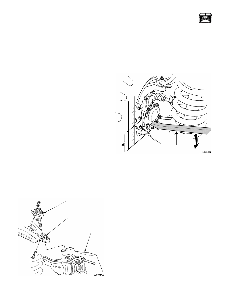
UPPER BALL JOINT REPLACEMENT
Removal
1.
Remove wheel.
2.
Raise and support lower control arm.
3.
Disconnect the p-clamp securing the vent line and speed
sensor lead to the upper control arm.
4.
Remove cotter pin and slotted nut from upper ball joint
(Figure 9-6).
5.
Remove four locknuts, bolts, eight washers and upper ball
joint from upper control arm.
6.
Separate upper ball joint from geared hub using ball joint
remover J–24319-B or equivalent. Remove ball joint.
Installation
1.
Position upper ball joint on upper control arm, ensuring
upper ball joint is placed above upper control arm
(Figure 9-6).
NOTE:
Check upper ball joint torque 15 minutes after initial
installation. Adjust if necessary.
2.
Install upper ball joint on upper control arm with four
bolts, locknuts and eight washers. Tighten 3/8 fine thread
locknuts to 30 lb-ft (41 N•m).
NOTE:
Do not loosen slotted nut to install cotter pin.
3.
Install upper ball joint on geared hub with slotted nut.
Using crowfoot and adapter, tighten slotted nut to 65 lb-ft
(88 N•m). Install cotter pin in slotted nut.
4.
Install the p-clamp securing the vent line and speed sensor
lead to the upper control arm.
5.
Lubricate upper ball joint.
6.
Install wheel.
Figure 9-6: Upper Ball Joint Replacement
LOWER BALL JOINT WEAR CHECK
1.
Support lower control arm with a jack or stand to unload
lower ball joint.
2.
Place prybar between lower arm at ball joint and geared
hub and measure vertical play obtained by moving pry bar
down (Figure 9-7). Maximum play should not
exceed 1/8"
(3.5 mm).
3.
Replace ball joint if end play exceeds the limit.
Figure 9-7: Lower Ball Joint Wear Check
UPPER CONTROL ARM
UPPER BALL JOINT
GEARED HUB
MEASURE
MOVEMENT
HERE
PRYBAR
Нет комментариевНе стесняйтесь поделиться с нами вашим ценным мнением.
Текст