Hummer H1 (2002+). Manual — part 133

_________________________________________________________
Steering System 8-39
®
05745159
POWER STEERING PUMP REPAIR
Disassembly
(Figures 8-72 through 8-77)
1.
Suction fluid from reservoir and disconnect fluid reservoir
hose from pump.
2.
Remove power steering pump pulley and bracket.
3.
Drain fluid from pump assembly (Figure 8-72).
4.
Remove two mounting studs from pump assembly.
NOTE: Fitting assembly is spring loaded. Remove care-
fully to avoid losing parts.
5.
Remove fitting assembly and O-ring seal. Discard O-ring
seal.
6.
Remove flow control valve and valve spring from pump
body.
Figure 8-72: Pump Assembly
Figure 8-73: Reservoir Removal
CAUTION: Do not overtighten vise as pump body could
be distorted.
7.
Place pump body in vise (Figure 8-73).
8.
Tap lightly around edge of housing.
9.
Remove housing and O-ring seal from pump body.
Discard O-ring seal.
10. Remove three O-ring seals from pump body and discard.
(Figure 8-74).
11. Remove magnet from pump body and discard.
7-S08-062.2
HOUSING
PUMP BODY
MOUNTING STUD
VALVE SPRING
O-RING SEAL
FITTING ASSEMBLY
FLOW CONTROL VALVE
PUMP
ASSEMBLY
MOUNTING STUD
HOUSING
O-RING SEAL
PUMP BODY
PUMP
SHAFT
4-1-00
8-40
Steering System
__________________________________________________________
®
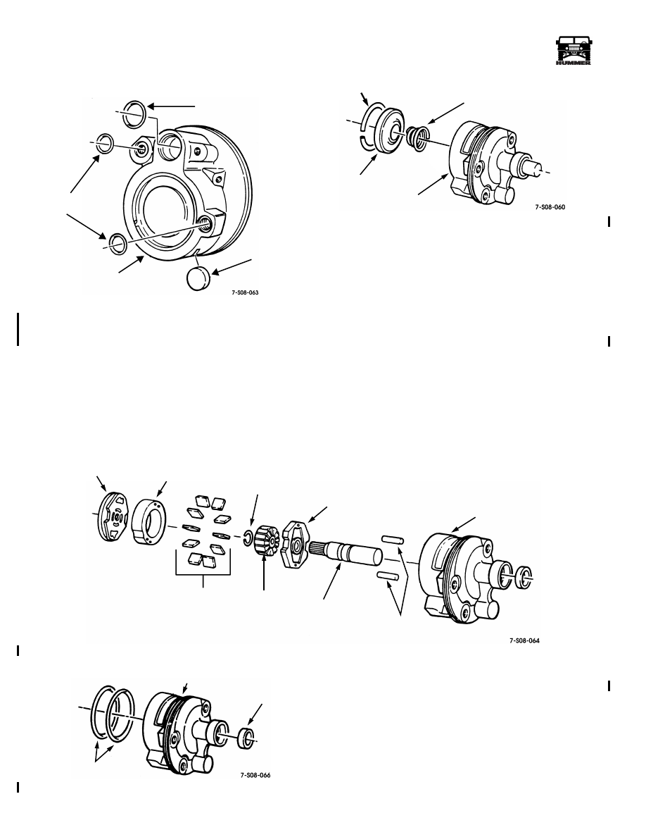
Figure 8-74: “O” Ring Seal Removal
12. Remove retaining ring from pump body (Figure 8-75).
13. Remove end plate and pressure plate spring from pump
body.
Figure 8-75: End Plate Removal
CAUTION: If end of driveshaft in steering pump housing
is corroded, clean with an abrasive crocus cloth before
removing shaft. Failure to do so may result in damage to
shaft bushing. If bushing is damaged, replace power
steering pump assembly.
14. Tap lightly on driveshaft until pressure plate is free
15. Remove pressure plate (Figure 8-76).
16. Remove pump ring and vanes from pump rotor.
17. Remove driveshaft, rotor, and thrust plate assembly from
pump body.
18. Remove retaining ring from driveshaft.
19. Remove rotor from driveshaft.
20. Remove thrust plate from driveshaft.
21. Remove dowel pins from pump body.
Figure 8-76: Pressure Plate and Rotor Removal
Figure 8-77: Seal Removal
22. Remove two O-ring seals from pump body. Discard O-
ring seals (Figure 8-77).
23. Remove driveshaft seal from pump body. Discard
driveshaft seal.
O-RING SEAL
O-RING
MAGNET
PUMP BODY
SEALS
RETAINING RING
PRESSURE PLATE SPRING
END PLATE
PUMP BODY
PRESSURE PLATE
PUMP RING
RETAINING RING
THRUST PLATE
PUMP BODY
VANES
ROTOR
DRIVESHAFT
DOWEL PINS
O-RING SEALS
PUMP BODY
DRIVESHAFT
SEAL
4-1-00

_________________________________________________________
Steering System 8-41
®
05745159
Cleaning and Inspection
(Figure 8-78)
NOTE: Clean all components, examine for wear or dam-
age, and replace if necessary.
1.
Inspect flow control valve and valve spring for damage.
2.
Inspect studs for damage.
3.
Inspect fitting for damage.
4.
Inspect housing for damage.
5.
Inspect remaining components for damage. Replace power
steering pump if any component is damaged.
Figure 8-78: Cleaning and Inspection
POWER STEERING PUMP
STUD
FLOW CONTROL VALVE
FITTING
VALVE SPRING
STUD
PUMP BODY
PRESSURE
PLATE
ROTOR
DRIVESHAFT
HOUSING
4-1-00
8-42
Steering System
__________________________________________________________
®
Assembly
(Figures 8-72 through 8-83)
NOTE: For general assembly instructions refer to Sec-
tion 2.
1.
Install O-ring seal in bottom groove of pump body
(Figure 8-79).
2.
Install driveshaft seal in pump body.
3.
Install rotor on thrust plate.
4.
Insert splined end of driveshaft through thrust plate and
rotor.
5.
Install retaining ring on driveshaft.
6.
Install dowel pins in pump body.
7.
Install driveshaft and rotor assembly in pump body.
CAUTION: To avoid damage to equipment, install pump
ring with arrow pointing up.
8.
Align dowel pins and small holes In pump ring.
9.
Install pump ring in pump body.
CAUTION: To avoid damage to equipment, install vanes
in rotor with rounded edges facing outward.
10. Install ten vanes in rotor.
CAUTION: To avoid damage to equipment, install pres-
sure plate with spring groove facing upward.
11. Install pressure plate on pump ring ensuring center
notches in pressure plate align with dowel pins.
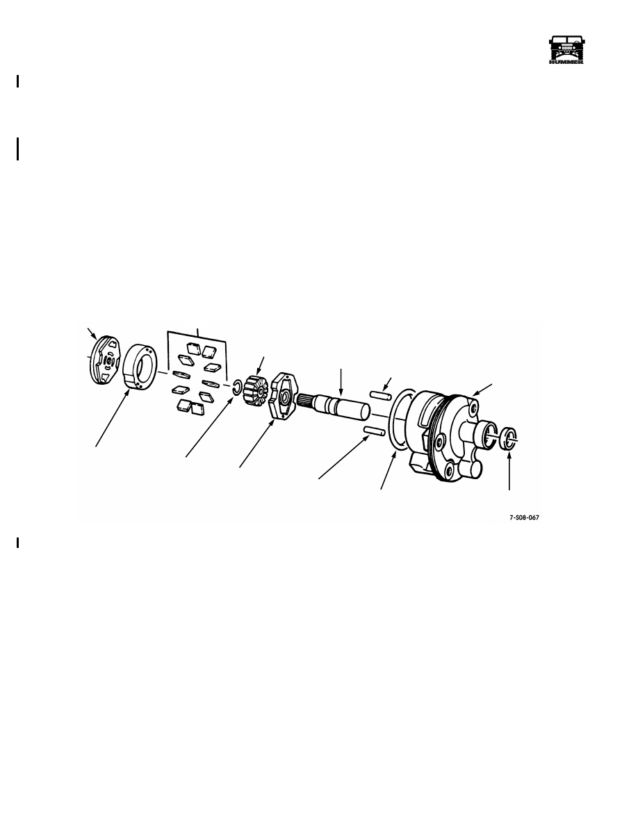
Figure 8-79: Pressure Plate and Rotor Installation
PRESSURE PLATE
VANES
ROTOR
DRIVESHAFT
DOWEL PIN
PUMP BODY
PUMP RING
RETAINING RING
THRUST PLATE
DOWEL PIN
O-RING SEAL
DRIVESHAFT SEAL
4-1-00
Нет комментариевНе стесняйтесь поделиться с нами вашим ценным мнением.
Текст