Hummer H1 (2002+). Manual — part 134
_________________________________________________________
Steering System 8-43
®
05745159
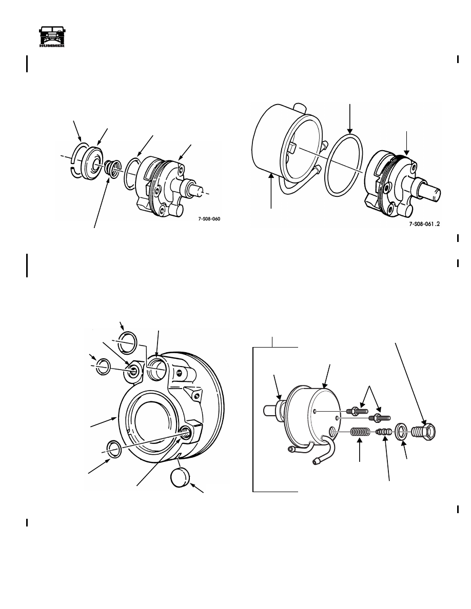
12. Install O-ring seal in center groove in pump body
(Figure 8-80).
13. Install pressure plate spring in pump body.
14. Install end plate and retaining ring in pump body.
Figure 8-80: End Plate Installation
15. Install magnet in pump body (Figure 8-81).
16. Install O-ring seal into control valve cavity and two O-ring
seals into threaded holes.
Figure 8-81: “O” Ring Installation
17. Install O-ring seal on pump body (Figure 8-82).
18. Install housing on pump body.
Figure 8-82: “O” Ring Installation
19. Install two mounting studs on pump assembly. Tighten
studs to 35 N.m 26 Ib-ft) (Figure 8-83).
20. Install valve spring and flow control valve in pump body.
21. Install O-ring seal and fitting assembly in pump body.
Tighten fitting in pump body to 50 N.m (37 Ib-ft.).
22. Install power steering pump, pulley and bracket.
Figure 8-83: Final Assembly
RETAINING RING
END PLATE
O-RING SEAL
PUMP BODY
PRESSURE PLATE SPRING
O-RING SEAL
CONTROL VALVE CAVITY
O-RING SEAL
THREADED HOLE
PUMP BODY
O-RING SEAL
THREADED HOLE
7-S08-063
MAGNET
HOUSING
O-RING SEAL
PUMP BODY
7-S08-062.2
HOUSING
MOUNTING STUD
VALVE SPRING
PUMP
FLOW CONTROL VALVE
O-RING SEAL
FITTING ASSEMBLY
BODY
PUMP ASSEMBLY
4-1-00
8-44
Steering System
__________________________________________________________
®
POWER STEERING SYSTEM FLUSHING
The power steering system can be flushed but only when the
fluid does not contain metal particles, foreign material, or de-
bris from a gear or pump failure. Flushing is recommended
only under the following circumstances:
• incorrect fluid added to system
• system filled with incorrect fluid
• water in the fluid
• burned, overheated fluid
Flushing Procedure
1.
Raise front wheels just enough for them to turn freely.
2.
Disconnect fluid return line at pump. Then plug pump
return port with rubber cap and hose clamp.
3.
Position and secure pump return line in drain pan.
4.
Have container of fresh power steering fluid handy. Pump
reservoir will need refilling as old fluid is pumped into
drain pan.
5.
Start and run the engine at curb idle speed.
6.
Have helper slowly turn steering wheel back and forth
about 3/4 turn in each direction.
7.
Continue procedure until only fresh fluid comes out of
return line.
8.
Stop engine, reconnect pump return line, and add power
steering fluid as needed.
9.
Purge air from system. Refer to procedure in this section.
10. Stop engine and check fluid level and condition. Repeat
flushing procedure if any old fluid is still evident in
reservoir fluid.
STEERING SPECIFICATIONS
Recommended fluid is Dextron III.
Steering Gear Adjustment Preload Torques
Wormshaft bearing . . . . . . 6 to 15 lb-in (0.7 to 1.7 N•m)
Pitman shaft overcenter . . . .. 6 to 10 lb-in (0.7 to 1.1 N•m)
NOTE: Overcenter preload is in addition to wormshaft bearing
preload. For example, overcenter preload should produce a
combined final torque ranging from 12 to 25 inch-pounds.
Torque Specifications
Adjuster Plug Locknut. . . . . . . . . 80 lb-ft (109 N•m)
Adjuster Screw Locknut . . . . . . . . 35 lb-ft (47 N•m)
Ball Guide Clamp Bolts. . . . . . . . . 36 lb-ft (49 N•m)
Pressure Hose Fittings (at gear). . . . . . 25 lb-ft (34 N•m)
Rack Piston Plug. . . . . . . . . . 111 lb-ft (150 N•m)
Side Cover Bolts. . . . . . . . . . . 44 lb-ft (60 N•m)
Steering Pump Flow Rates and Operating
Pressures
Minimum Flow Rate In Gallons/Liters Per Minute = 1.32 gpm
(5.0 liters/min) @ 465 rpm
Maximum Flow Rate In Gallons/Liters Per Minute = 3.1 to 3.5
gpm (11.7 to 13.2 liters/min) @ 1500 rpm
Minimum Pump Output Pressure 1200 psi (8274 kPa)
Maximum Pump Output Pressure: 1,475 - 1,515 psi (10,170 -
10,446 kPa)
NOTE: Pump output pressures are controlled by the pump re-
lief valve setting

_________________________________________________________
Steering System 8-45
®
05745159
ESSENTIAL TOOLS
Procure from Kent-Moore.
Tool
Description
J–24319-B
Steering Linkage and Tie-Rod Puller
J–25033-C
Pump Pulley Installer
J–33141
Adapter Fittings (used with J–25323)
J–25034-C
Pump Pulley Remover
J–25323
Power Steering System Analyzer
J–42548
Puller, Pitman Arm
J–8092
Universal Driver Handle
J
–
25033-C
J
–
25034-C
J
–
25323
J
–
33141
J
–
42548
J
–
24319-B
J
–
8092

8-46
Steering System
__________________________________________________________
®
SPECIAL TOOLS
Procure from Kent-Moore.
Tool
Description
J–6219
Pitman Shaft Seal Installer
J–6221
Stub Shaft Bearing and Seal Remover/Installer
J–6278 (or J–21551)
Pitman Shaft Bearing Remover/Installer
J–7624
Spanner Wrench (Adjuster Plug)
J–7754-C
Inch-Pound Torque Wrench (Over-Center Preload)
J–21552
Rack Piston Arbor
J
–
4245
J
–
6219
J
–
6221
J
–
6278 or J
–
21551
J
–
7624
J
–
7754-C
J
–
8092 or J
–
7079
J
–
21552
Нет комментариевНе стесняйтесь поделиться с нами вашим ценным мнением.
Текст