Hummer H1 (2002+). Manual — part 110
______________
Wheels and Tires/Central Tire Inflation System (CTIS) 6-55
®
05745159
Installation
NOTE: Ensure that any new fittings have pipe sealant pre-ap-
plied to threads. If none is present, apply a pipe sealant to fit-
ting threads.
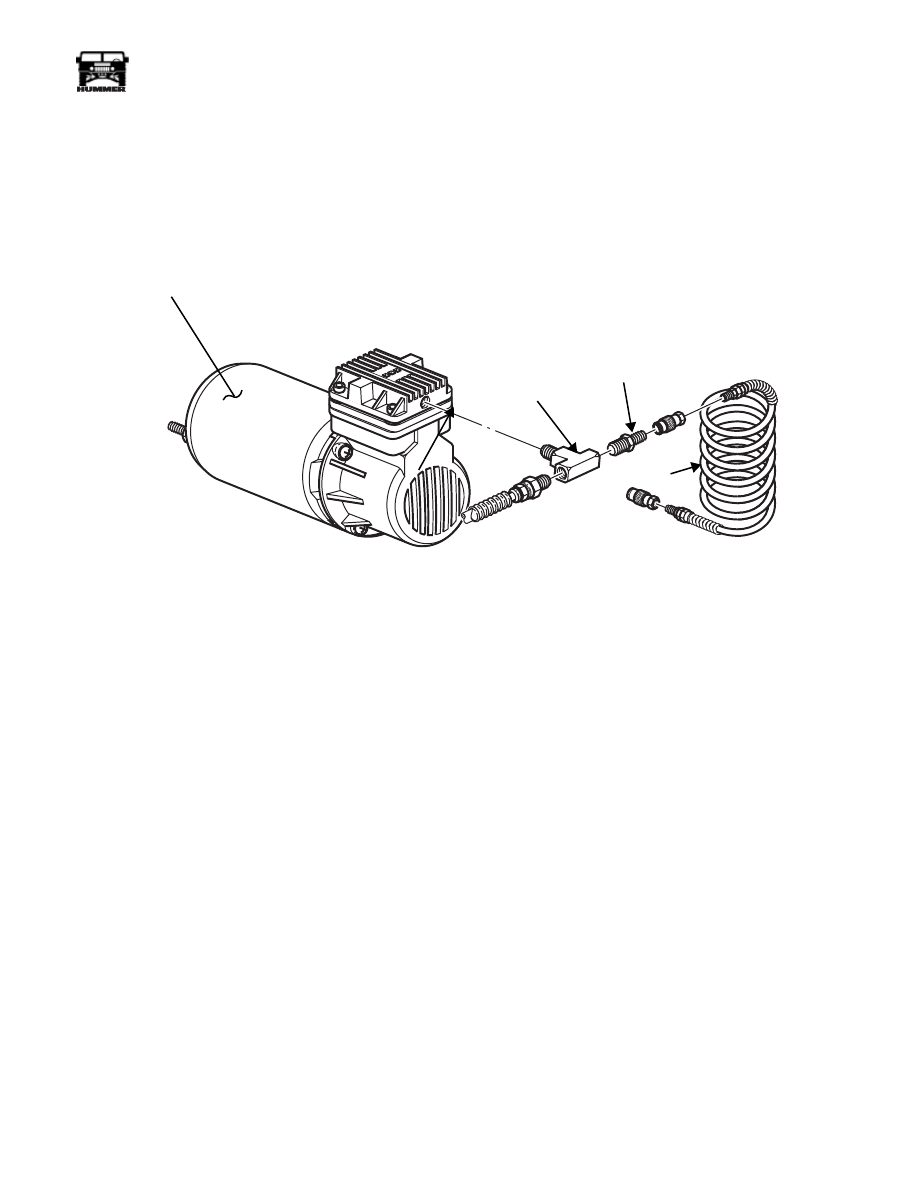
1.
Secure auxiliary air valve to existing tee (Figure 6-81).
2.
Connect tires to CTIS by pushing in quick-disconnect
valve body until valve tee section locks (clicks) into place.
Perform this procedure on remaining three wheels
(Figure 6-80).
3.
Start engine and check CTIS for air leaks around installed
fittings.
4.
Lower and secure hood.
Figure 6-81: CTIS Auxiliary Air Hose
9-S06-017
COMPRESSOR
AIR HOSE
EXISTING TEE
AUXILIARY
AIR VALVE

6-56
Wheels and Tires/Central Tire Inflation System (CTIS)
_______________
®
SPECIAL TOOLS
Tool No.
Description
05710216
Internal tubeless tire repair kit
05710215
External tubeless tire repair kit
05710215
05710216
________________________________________________________________________________
7-1
®
05745159
Section 7 Brake System
TABLE OF CONTENTS
Anti-lock Brake System (ABS) and Automatic Traction Control,
TorqTrac 4™ (TT4™) . . . . . . . . . . . . . . . . . . . . . . . . . . . . . . . . .7-34
ABS ECU Replacement . . . . . . . . . . . . . . . . . . . . . . . . . . . .7-50
ABS Modulator Replacement . . . . . . . . . . . . . . . . . . . . . . .7-48
ABS/TT4 Diagnostics . . . . . . . . . . . . . . . . . . . . . . . . . . . . .7-34
Fault Diagnostic Procedure . . . . . . . . . . . . . . . . . . . . . . . .7-34
Fuse and Relay Replacement . . . . . . . . . . . . . . . . . . . . . . .7-50
System Description . . . . . . . . . . . . . . . . . . . . . . . . . . . . . . .7-34
System Operation . . . . . . . . . . . . . . . . . . . . . . . . . . . . . . . .7-34
Bench Bleeding . . . . . . . . . . . . . . . . . . . . . . . . . . . . . . . . . .7-12
Bleeding . . . . . . . . . . . . . . . . . . . . . . . . . . . . . . . . . . . . . . . .7-12
Replacement . . . . . . . . . . . . . . . . . . . . . . . . . . . . . . . . . . . .7-11
Bleeding Instructions . . . . . . . . . . . . . . . . . . . . . . . . . . . . . .7-8
Brake Line Replacement . . . . . . . . . . . . . . . . . . . . . . . . . . .7-14
Brake Rotor . . . . . . . . . . . . . . . . . . . . . . . . . . . . . . . . . . . . .7-32
Burnishing Linings and Rotors . . . . . . . . . . . . . . . . . . . . .7-10
Caliper Overhaul, Rear . . . . . . . . . . . . . . . . . . . . . . . . . . . .7-29
Description . . . . . . . . . . . . . . . . . . . . . . . . . . . . . . . . . . . . . . .7-1
Diagnosis . . . . . . . . . . . . . . . . . . . . . . . . . . . . . . . . . . . . . . . .7-2
Disc Brake Caliper Repair, Front . . . . . . . . . . . . . . . . . . . .7-27
Front Service Brake Caliper . . . . . . . . . . . . . . . . . . . . . . . .7-10
Hydro-Boost System Diagnosis. . . . . . . . . . . . . . . . . . . . . . 7-7
Left Parking Brake Cable Replacement . . . . . . . . . . . . . . 7-23
Pad Replacement, Service Brake. . . . . . . . . . . . . . . . . . . . . 7-9
Parking Brake Cable Replacement, L . . . . . . . . . . . . . . . . 7-24
Parking Brake Cable Replacement, R . . . . . . . . . . . . . . . . 7-23
Parking Brake Lever Adjustment. . . . . . . . . . . . . . . . . . . . 7-33
Parking Brake Lever Replacement . . . . . . . . . . . . . . . . . . 7-26
Parking Brake Switch Replacement . . . . . . . . . . . . . . . . . 7-33
Pedal Replacement, Service Brake . . . . . . . . . . . . . . . . . . 7-17
Proportioning Valve Replacement. . . . . . . . . . . . . . . . . . . 7-17
Rotor Replacement, Service Brake . . . . . . . . . . . . . . . . . . 7-17
Troubleshooting . . . . . . . . . . . . . . . . . . . . . . . . . . . . . . . . . . 7-4
Rear Dual Service/Parking Brake
Adjustment. . . . . . . . . . . . . . . . . . . . . . . . . . . . . . . . . . . . . . 7-25
Caliper Replacement. . . . . . . . . . . . . . . . . . . . . . . . . . . . . . 7-20
Pad Replacement . . . . . . . . . . . . . . . . . . . . . . . . . . . . . . . . 7-18
Rod Replacement . . . . . . . . . . . . . . . . . . . . . . . . . . . . . . . . 7-25
Speed Sensor Replacement. . . . . . . . . . . . . . . . . . . . . . . . . . . . 7-49
Tone Wheel Replacement. . . . . . . . . . . . . . . . . . . . . . . . . . . . . . 7-50
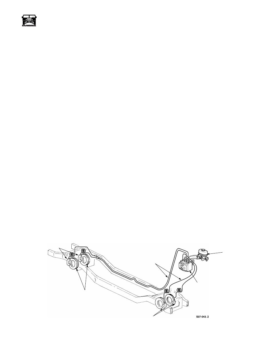
POWER BRAKE SYSTEM DESCRIPTION
The hydraulic power disc brake system is a four-wheel, inboard-
mounted design. The dual reservoir master cylinder stores brake
fluid and converts mechanical brake pedal force to hydraulic
pressure. The proportioning valve provides balanced front-to-rear
braking and activates the brake warning lamp in case of a brake
hydraulic system malfunction. The dual reservoir master cylinder
provides fluid for separate front and rear brake systems
(Figure 7-1). The hydro-boost provides power brake assist and is
operated by fluid pressure from the power steering pump. The
hydro-boost is equipped with an accumulator. The accumulator
stores nitrogen gas under pressure in
the event that both the normal assist and accumulator assist are
not available. The power steering pump provides hydraulic oil
pressure to operate the brake system’s hydro-boost feature. If the
power steering pump fails to supply hydraulic pressure to the hy-
dro-boost, the pressure stored in the accumulator will provide
enough hydraulic pressure for approximately four power-assisted
stops. Applying the parking brake prevents the rear brake rotors
from rotating and can also be used to help stop the vehicle in low
speed emergency situations.
The disc brakes are mounted on the output flanges of the front
and rear axle assemblies.
Figure 7-1: Brake System
BRAKE
BRAKE ROTORS
BRAKE CALIPERS
HYDRAULIC BRAKE
LINES
CALIPERS
MASTER
CYLINDER
ABS
MODULATOR
7-2
Brake System
______________________________________________________________
®
BRAKE SYSTEM DIAGNOSIS
Road Testing
1.
If red warning light is illuminated, note pedal action and
brake response.
2.
Check brake pedal response with transmission in Neutral
and engine running. Pedal should remain firm under
steady foot pressure. If pedal falls away, problem is either
in hydro-boost, master cylinder, or brakeline.
3.
During road test, make normal and firm brake stops in 25-
40 mph range. Note faulty brake operation such as pull,
grab, drag, noise, fade, pedal pulsation, etc. (noise and
pedal pulsation during an ABS event is normal).
4.
Inspect suspect brake components and refer to problem
diagnosis information for causes of various brake
conditions.
Component Inspection
Fluid leak points and dragging brake units can usually be lo-
cated without removing any components. The area around a
leak point will be wet with fluid. The components at a dragging
brake unit will be quite warm or hot to the touch.
During component inspection, pay particular attention to
heavily rusted/corroded brake components (e.g. rotors, caliper
pistons, lines, etc.).
Heavy accumulations of rust may be an indicator of rust and
corrosion damage to a brake component. It is wise to remove
surface rust in order to accurately determine the depth of rust
penetration and damage. Light surface rust is fairly normal and
not a major concern (as long as it is removed). However, heavy
rust buildup, especially on high mileage vehicles, may actually
cover structural damage to such important components as
brakelines and rotors.
Diagnosing Service Brake Problems
Brake Warning Light Operation
The red brake warning light will illuminate when the parking
brakes are applied, and when there is a low fluid level in the
brake fluid reservoir. If the light comes on, first verify that the
parking brakes are fully released. Then check pedal action and
fluid level. If a problem is confirmed, inspect the wheel brake
hydraulic system.
Pedal Falls Away
A brake pedal that falls away under steady foot pressure is gen-
erally the result of a system leak. The leak point could be at a
brakeline, fitting, hose, or caliper. Internal leakage in the mas-
ter cylinder caused by worn or damaged piston cups, may also
be the problem cause.
If leakage is severe, fluid will be evident at or around the leak-
ing component. However internal leakage in the master cylin-
der will not be physically evident. Refer to the cylinder test
procedure in this section.
Low Pedal
If a low pedal is experienced and the warning light is
not
on,
worn lining and worn rotors are the most likely cause.
If the red warning light is on, low fluid in the master cylinder is
the most likely cause. A leak at a caliper, brakeline, or brake
hose will cause the fluid level in the master cylinder reservoir
to become low, triggering the low fluid switch and the red
brake warning light.
Spongy Pedal
A spongy pedal is most often caused by air in the system.
However, substandard brake lines and hoses will also cause a
condition similar to a spongy pedal. The proper course of ac-
tion is to bleed the system, or replace suspect quality brake
lines and hoses.
Hard Pedal or High Pedal Effort
A hard pedal or high pedal effort may be due to lining that is
water soaked, contaminated, glazed, or badly worn.
Brake Drag
Brake drag occurs when the lining is in constant contact with
the rotor. Drag can occur at one wheel, all wheels, fronts only,
or rears only. It is a product of incomplete brakeshoe release.
Drag can be minor or severe enough to overheat the linings,
and rotors.
Brake drag also has a direct effect on fuel economy. If undetec-
ted, minor brake drag can be misdiagnosed as an engine or
transmission/torque converter problem.
Minor drag will usually cause slight surface glazing of the lin-
ing. It can also generate hard spots in rotors from the overheat-
cool down process. In most cases, the rotors, wheels and tires
are quite warm to the touch after the vehicle is stopped.
Severe drag can char the brake lining all the way through. It
can also distort and score rotors to the point of needing replace-
ment. The wheels, tires and brake components will be ex-
tremely hot. In severe cases, the lining may generate smoke as
it chars from overheating.
Нет комментариевНе стесняйтесь поделиться с нами вашим ценным мнением.
Текст