Hummer H1 (2002+). Manual — part 51

_____________________________________________
Transmission/Transfer Case 5-3
®
05745159
TRANSMISSION IDENTIFICATION
An I.D. plate is attached to the passenger side of each Hydra-
matic Transmission (Figure 5-2). The plate contains the model,
Hydra-matic type, model year, calendar year, and Julian calen-
dar date.
The I.D. plate information is required for correct service parts
ordering.
Figure 5-2: Transmission I.D. Plate Information
(Example Plate)
ELECTRONIC SHIFT CONTROL COMPONENTS
Upshifts and downshifts in overdrive and manual D ranges are
electronically controlled. Transmission electronic components
include (Figure 5-3):
• Automatic Transmission Fluid Temperature Sensor
• Automatic Transmission Fluid Pressure Manual Valve
Position switch
• Automatic Transmission Input (shaft) Speed Sensor
• Automatic Transmission Output(shaft) Speed Sensor
(Vehicle Speed Sensor)
• 1-2 and 2-3 shift solenoids
• Pressure Control Solenoid Valve
• Torque Converter Clutch Pulse Width Modulated Sole-
noid
• PCM (powertrain control module)
Additional inputs to the transmission PCM are provided by: the
engine coolant temperature sensor, Cruise Control, A/C re-
quest, electronic accelerator pedal, crankshaft position sensor,
and brake switch.
Adapt Function
The 4L80-E transmission uses a line pressure control system,
which has the ability to continuously adapt the system’s line
pressure. This compensates for normal wear and break in of the
following parts.
• The clutch fiber plates
• The seals
• The springs
The PCM maintains the following adapt parameters for the
transmission:
• Upshift Adapt - The PCM monitors the Automatic
Transmission Input (Shaft) Speed Sensor (A/T ISS) and
the Output or Vehicle Speed Sensor (VSS) during com-
manded shifts in order to determine if a shift is occur-
ring too fast or too slow. The PCM adjusts the signal to
the transmission pressure control solenoid valve in order
to maintain a set shift feel.
• Steady State Adapt - The PCM monitors the Automatic
Transmission Input (Shaft) Speed Sensor (A/T ISS) and
the Vehicle Speed Sensor (VSS) after a shift in order to
calculate the amount of slippage in that gear. The PCM
then adjusts the signal to the Transmission Pressure
Control Solenoid signal in order to maintain slippage
below a set amount.
Reset the Transmission Adapt functions when the transmission
is overhauled or replaced. To reset the Transmission Adapt
functions, use the Tech 1 Scan Tool.
TRANSMISSION
I.D. PLATE
JULIAN DATE
CALENDAR
YEAR
MODEL YEAR
(98 = 1998)
MODEL
HYDRA-MATIC
4L80-E/4L80-EHD
98
000
0
P
XX
5-4
Transmission/Transfer Case
______________________________________________
®
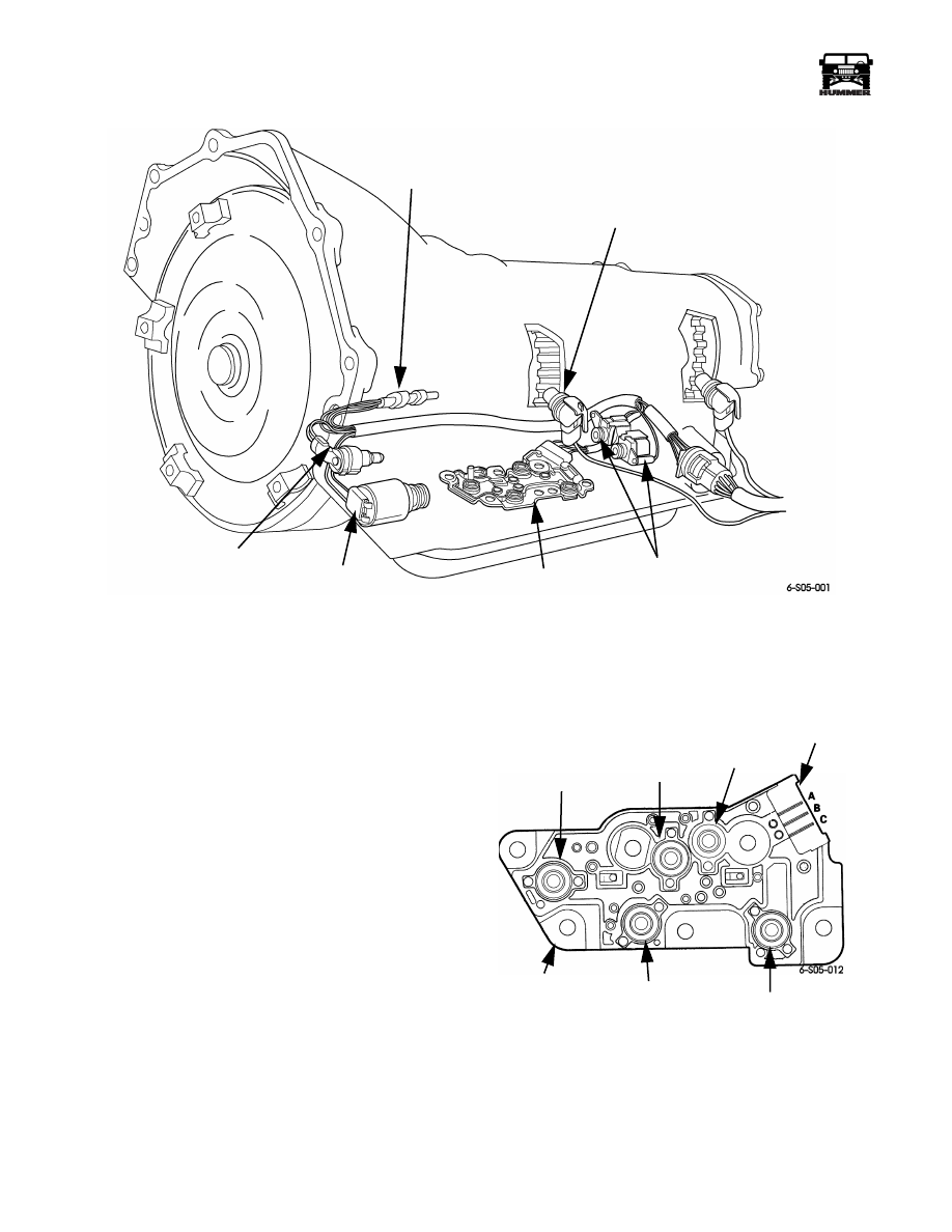
Figure 5-3: Transmission Shift Control Components
TRANSMISSION FLUID PRESSURE MANUAL
VALVE POSITION SWITCH
The pressure switch assembly is mounted on the valve body. It
contains five pressure switches in circuit with the PCM
(Figure 5-4). The switches are used to signal the PCM which
gear range has been selected.
Each pressure switch is activated by fluid pressure
(Figure 5-5). Fluid flow through the manifold is controlled by
the valve body manual valve (Figure 5-6).
The five pressure switches are closed only when fluid pressure
is applied. Fluid flow into the switch cavity presses the dia-
phragm downward against the contact element and switch con-
tact (Figure 5-4). Once the switch closes, it completes the
ground circuit to the PCM through one of the connector pins
(Figure 5-4).
The hydraulic and electrical schematics in Figure 5-6 illustrate
switch activation and fluid flow in third gear. The Drive and
PRND 4/3 switches are pressurized closing the circuit to con-
nector pin C (Figure 5-4). This changes the digital logic at Pin
C to O and the logic at Pins A and B to 1 (Figure 5-6). The
PCM reads this as third gear.
Figure 5-4: Pressure Switch and Connector
Identification
FLUID
TEMPERATURE
SENSOR
INPUT
SPEED
SENSOR
CONVERTER
CLUTCH
SOLENOID
PRESSURE
CONTROL
SOLENOID
PRESSURE
SWITCH
ASSEMBLY
SHIFT
SOLENOIDS
REVERSE
SWITCH
PRND 4/3
SWITCH
LO (1-2)
SWITCH
THREE PIN
CONNECTOR
PRESSURE
SWITCH
ASSEMBLY
PRND 4
SWITCH
DRIVE
SWITCH

_____________________________________________
Transmission/Transfer Case 5-5
®
05745159
Figure 5-5: Pressure Switch Actuation
Figure 5-6: Hydraulic/Electrical Circuitry for Pressure Switch Assembly (Third Gear Shown)
CONTACT
BODY
FLUID
O-RING
DIAPHRAGM
GROUND
CONTACT
ELEMENT
SWITCH
CONTACT
CONTACT
CONTACT
ELEMENT
SWITCH
CONTACT
GROUND
DIAPHRAGM
O-RING
FLUID
BODY
5-6
Transmission/Transfer Case
______________________________________________
®
AUTOMATIC TRANSMISSION INPUT (SHAFT)
SPEED SENSOR AND OUTPUT (SHAFT) SPEED
SENSOR (VEHICLE SPEED SENSOR)
The input and vehicle speed sensors are variable reluctance,
magnetic pickup units (Figure 5-7). They consist of a perma-
nent magnet surrounded by a wire coil. The sensors are
mounted in the driver side of the transmission case and the top
of the transfer case at the rear.
The vehicle speed sensor is positioned opposite the speedome-
ter tone wheel in the rear of the transfer case. The input sensor
is opposite the machined teeth on the forward clutch housing in
the transmission (Figure 5-7). The tone wheel and gear teeth
interrupt the sensor magnetic field as they rotate. This induces
an AC current in each sensor coil. The vehicle sensor provides
a voltage signal proportional to vehicle speed. The input sensor
signal indicates transmission shaft/turbine speed. Both sensor
signals are used by the PCM to determine shift speed, pattern,
and converter clutch apply.
Sensor signals reaching the PCM are converted to a square
wave form (Figure 5-7). The wave forms correspond to the
teeth on the speedometer tone wheel and forward clutch. The
increase in shaft speed will cause more teeth to interrupt the
sensor magnetic field in a given time. This is reflected in an in-
crease in the number of wave forms sent to the PCM. The wave
forms are compared to a fixed signal voltage in the PCM to de-
termine speeds.
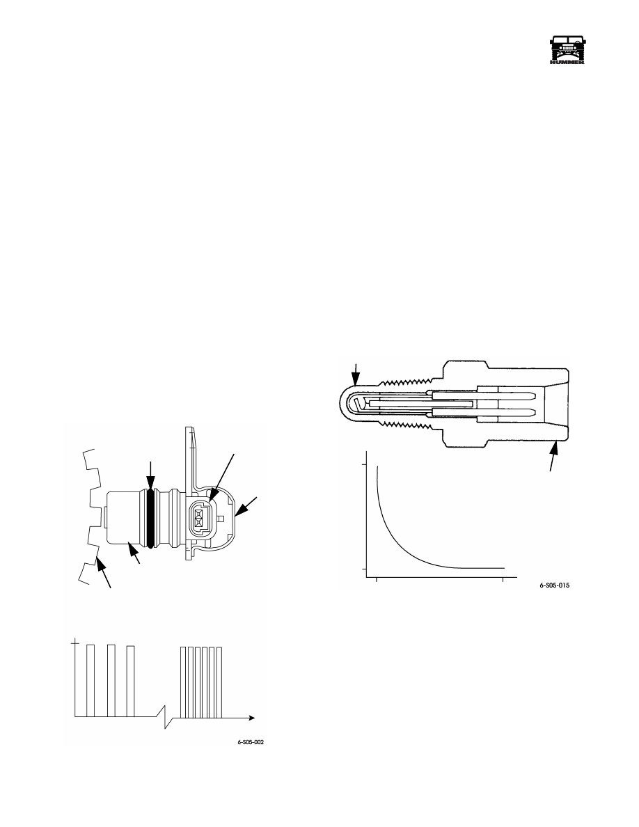
Figure 5-7: Transmission Speed Sensor Signal Form
TRANSMISSION FLUID TEMPERATURE SENSOR
The fluid temperature sensor is mounted on the internal trans-
mission harness. Failure of the sensor constitutes wiring har-
ness replacement. It is a temperature sensitive resistor more
commonly known as a thermister (Figure 5-8). Low fluid tem-
perature produces high resistance. The PCM controls torque
converter clutch apply based on sensor input signals.
The PCM will not allow converter clutch apply when fluid
temperature is below 68°F (20°C). At higher fluid tempera-
tures, the PCM will apply or release the converter clutch as fol-
lows:
• Apply the clutch in second, third, fourth when fluid tem-
perature exceeds 250°F (122°C).
• Release the clutch and prevent apply in any gear range
when fluid temperature reaches or exceeds 300°F
(150°C).
• Prevent converter clutch apply and set a-fault code
when fluid temperature reaches 310°F (154°C).
Figure 5-8: Temperature Sensor
O-RING
ELECTRICAL
CONNECTOR
SPEED
SENSOR
MAGNETIC PICKUP
(MAGNET AND COIL)
LOW SPEED
HIGH SPEED
TIME
SIGNAL VOLTS
5.0
CONDITIONED SQUARE WAVE SIGNAL
FOWARD CLUTCH
GEAR TEETH OR
SPEEDOMETER
TONE WHEEL
SENSOR
ELEMENT
TEMPERATURE
SENSOR
16,000
133
-10°C
+16°F
110°C
230°F
Нет комментариевНе стесняйтесь поделиться с нами вашим ценным мнением.
Текст