Hummer H1 (2002+). Manual — part 50
_________________________________________________________
Cooling System 4-15
®
05745159
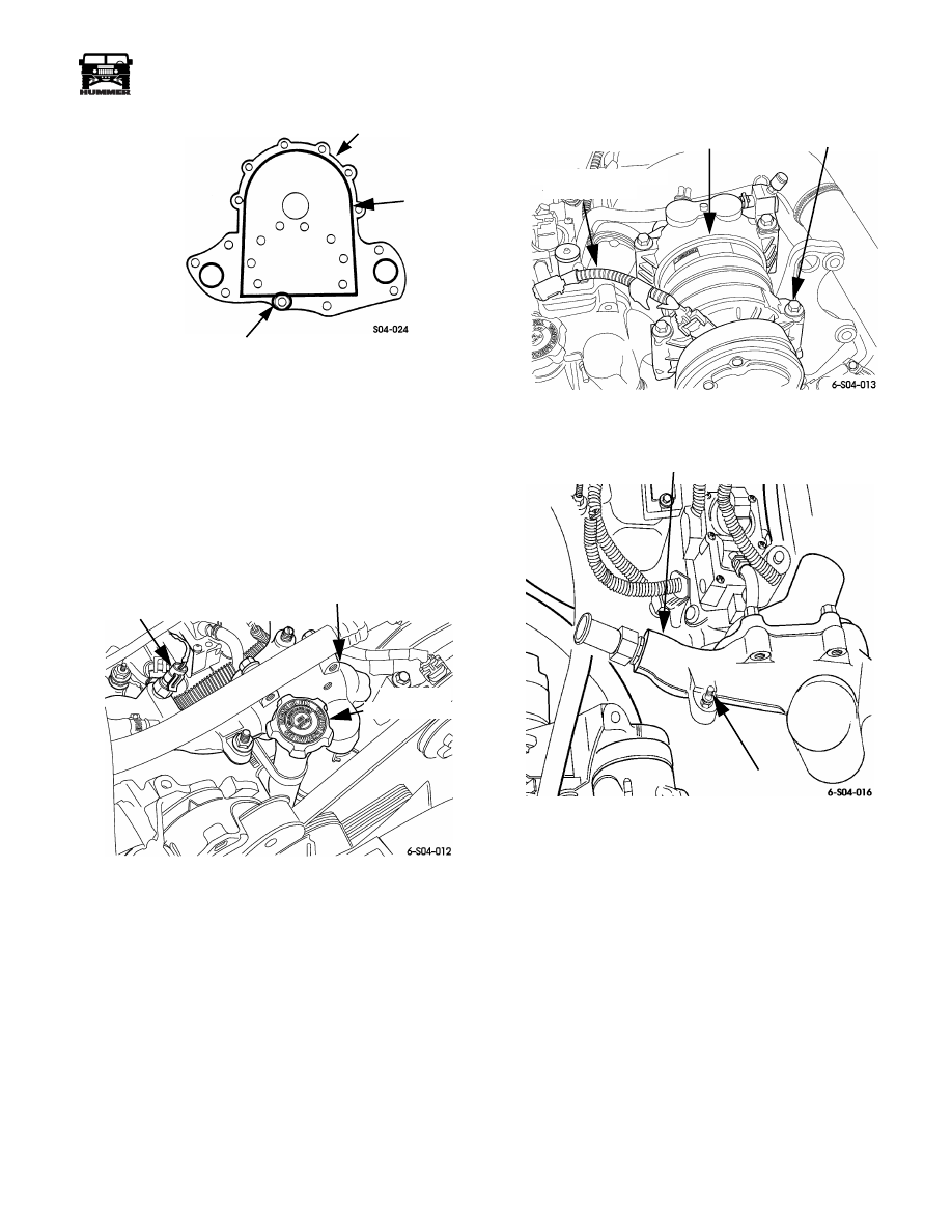
Figure 4-28: Backing Plate Sealer Application
WATER CROSSOVER SERVICE
Removal
1.
Drain engine coolant to below level of crossover.
2.
Disconnect heater, surge tank, and radiator hoses at
crossover.
3.
Disconnect coolant temperature sensor wires (Figure 4-29).
Figure 4-29: Filler Tube and Temperature
Sensor Locations
4.
Remove oil filler tube attaching nuts and remove filler
tube (Figure 4-29).
5.
Disconnect A/C compressor clutch wires (Figure 4-30).
6.
Remove compressor clutch mounting bolts. Lift
compressor out of bracket and move it aside for access to
crossover bolts and nuts.
7.
Remove water crossover attaching bolts/nuts (Figure 4-31).
8.
Remove crossover and gaskets.
9.
If crossover will be replaced, transfer air bleed valve and
coolant temperature sensor to new crossover. Also transfer
thermostats if necessary. Use Loctite PST on valve and
sensor threads to ensure proper seal.
Figure 4-30: Compressor Clutch Bolt and
Connector Location
Figure 4-31: Water Crossover Attaching Hardware
Installation
1.
Apply Permatex Ultra Black or no. 2 sealer to both sides
of crossover gaskets. Then position gaskets on cylinder
heads.
2.
Align and install crossover. Tighten crossover nuts/bolts
to 25-37 lb. ft. (34-50 N•m) torque.
3.
Install oil filler tube. Tighten attaching nuts to 13-20 lb. ft.
(18-27 N•m) torque.
4.
Connect hoses to water crossover.
5.
Install A/C compressor in bracket and tighten bolts.
6.
Connect wires to coolant temperature sensor.
7.
Refill and bleed engine cooling system.
BACKING PLATE
ENCIRCLE THIS BOLT
HOLE WITH SEALER
SEALER
BEAD
COOLANT
TEMPERATURE
SENSOR
CROSSOVER
OIL FILLER
CAP AND TUBE
A/C COMPRESSOR
COMPRESSOR
BOLT (4)
COMPRESSOR CLUTCH
CONNECTOR
WATER CROSSOVER
STUD NUT
4-16
Cooling System
__________________________________________________________
®
SERPENTINE BELT REPLACEMENT
1.
Insert square lug of half-inch drive breaker bar in belt ten-
sioner. Then move tensioner counterclockwise to loosen
belt (Figure 4-32).
2.
Remove belt from pulleys (Figure 4-33).
3.
Position half-inch drive breaker bar in belt tensioner and
move tensioner counterclockwise and position serpentine
belt on pulleys as shown (Figure 4-33).
4.
Release belt tensioner. Tensioner will automatically set
belt tension when released.
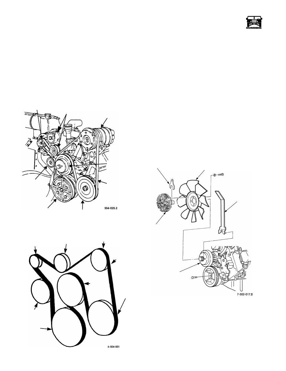
Figure 4-32: Serpentine Belt Tensioner Location
Figure 4-33: Serpentine Belt Routing
FAN AND CLUTCH ASSEMBLY SERVICE
Removal
1.
Insert spanner J–41240-1 in holes in water pump pulley
(Figure 4-34).
2.
Use the spanner to hold the water pump shaft and wrench
J–41240-5A to break the nut loose securing the fan clutch
to the water pump.
3.
Remove bolts attaching fan to fan clutch.
4.
Remove fan clutch-to-water pump nut.
5.
Remove fan and clutch from water pump.
Installation
6.
Slide fan onto clutch and install bolts finger tight.
7.
Install fan and clutch assembly on water pump shaft
(Figure 4-34).
8.
Hold water pump shaft with spanner J–41240-1 and
tighten clutch nut to 80-100 lb-ft (108-135 N•m) with
wrench J–41240-5A.
9.
Torque fan bolts to 15-20 lb-ft (20-27 N•m).
Figure 4-34: Fan and Clutch Assembly
GENERATOR
PULLEY
WATER PUMP
PULLEY
CRANKSHAFT
PULLEY
POWER STEERING
PUMP PULLEY
SERPENTINE
BELT
VACUUM
A/C COMPRESSOR
(OR IDLER PULLEY
BELT TENSIONER
AND PULLEY
PUMP
WITHOUT A/C)
CRANKSHAFT
PULLEY
VACUUM PUMP
WATER
PUMP
PULLEY
GENERATOR
PULLEY
TENSIONER
PULLEY
A/C COMPRESSOR
OR IDLER PULLEY
SERPENTINE
BELT
POWER
STEERING
PUMP
PULLEY
CLUTCH
FAN
SPANNER
WRENCH
WATER
PUMP
PULLEY
________________________________________________________________________________
5-1
®
05745159
Section 5 Transmission/Transfer Case
TABLE OF CONTENTS
Bulkhead, 76 Way . . . . . . . . . . . . . . . . . . . . . . . . . . . . . . . . . . . . . .5-28
Converter Housing
Extension Housing Bushing and Seal. . . . . . . . . . . . . . . . . . . . .5-169
Flexplate Replacement . . . . . . . . . . . . . . . . . . . . . . . . . . . . . . . . .5-139
Front Output Shaft
Bearing and Seal Replacement . . . . . . . . . . . . . . . . . . . . . 5-166
Seal Replacement . . . . . . . . . . . . . . . . . . . . . . . . . . . . . . . . 5-155
Input Gear Bearing Replacement . . . . . . . . . . . . . . . . . . . . . . . .5-168
Instrument Panel, 56 Way . . . . . . . . . . . . . . . . . . . . . . . . . . . . . . .5-31
Mainshaft Pilot Bearing Replacement . . . . . . . . . . . . . . . . . . . .5-168
PCM, 24 Way, Brown . . . . . . . . . . . . . . . . . . . . . . . . . . . . . . . . . . . .5-39
PCM, 32 Way, Blue. . . . . . . . . . . . . . . . . . . . . . . . . . . . . . . . . . . . . 5-37
PCM, 32 Way, Brown . . . . . . . . . . . . . . . . . . . . . . . . . . . . . . . . . . . .5-35
Propeller Shaft
Torque Specifications . . . . . . . . . . . . . . . . . . . . . . . . . . . . . .5-181
Installation . . . . . . . . . . . . . . . . . . . . . . . . . . . . . . . . . . . . . . .5-147
Removal . . . . . . . . . . . . . . . . . . . . . . . . . . . . . . . . . . . . . . . . .5-143
Service . . . . . . . . . . . . . . . . . . . . . . . . . . . . . . . . . . . . . . . . . .5-144
Shift Linkage Adjustment . . . . . . . . . . . . . . . . . . . . . . . . . . . . . .5-148
Status Center, 8 Way, LH . . . . . . . . . . . . . . . . . . . . . . . . . . . . . . . .5-34
Torque Converter/Oil Pump Seal . . . . . . . . . . . . . . . . . . . . . . . . .5-139
Transfer Case
Assembly . . . . . . . . . . . . . . . . . . . . . . . . . . . . . . . . . . . . . . . .5-170
Cleaning and Inspection . . . . . . . . . . . . . . . . . . . . . . . . . . . .5-165
Description . . . . . . . . . . . . . . . . . . . . . . . . . . . . . . . . . . . . . . .5-149
Diagnosis . . . . . . . . . . . . . . . . . . . . . . . . . . . . . . . . . . . . . . . .5-151
Disassembly and Overhaul . . . . . . . . . . . . . . . . . . . . . . . . .5-157
Fluid Change . . . . . . . . . . . . . . . . . . . . . . . . . . . . . . . . . . . . .5-155
Fluid Level . . . . . . . . . . . . . . . . . . . . . . . . . . . . . . . . . . . . . . .5-150
Guide Cable Replacement . . . . . . . . . . . . . . . . . . . . . . . . . 5-154
Identification. . . . . . . . . . . . . . . . . . . . . . . . . . . . . . . . . . . . . 5-150
Installation . . . . . . . . . . . . . . . . . . . . . . . . . . . . . . . . . . . . . . 5-156
Oil Cooler . . . . . . . . . . . . . . . . . . . . . . . . . . . . . . . . . . . . . . . .5-150
Operating Ranges . . . . . . . . . . . . . . . . . . . . . . . . . . . . . . . . .5-150
Recommended Lubricant . . . . . . . . . . . . . . . . . . . . . . . . . . 5-150
Removal . . . . . . . . . . . . . . . . . . . . . . . . . . . . . . . . . . . . . . . . .5-156
Shift Rod Service . . . . . . . . . . . . . . . . . . . . . . . . . . . . . . . . . .5-153
Shifting . . . . . . . . . . . . . . . . . . . . . . . . . . . . . . . . . . . . . . . . . .5-151
Speed Sensor and Switch Replacement . . . . . . . . . . . . . .5-154
Torque Specifications . . . . . . . . . . . . . . . . . . . . . . . . . . . . . .5-181
Vent Line Replacement . . . . . . . . . . . . . . . . . . . . . . . . . . . .5-153
Cooler Line and Bypass Valve Service . . . . . . . . . . . . . . . .5-133
Diagnosis . . . . . . . . . . . . . . . . . . . . . . . . . . . . . . . . . . . . . . . . .5-11
Electronic Shift Control Components . . . . . . . . . . . . . . . . . . .5-3
Engine Sensor Inputs . . . . . . . . . . . . . . . . . . . . . . . . . . . . . . . .5-9
Essential Tools. . . . . . . . . . . . . . . . . . . . . . . . . . . . . . . . . . . .5-182
Fill Tube Replacement . . . . . . . . . . . . . . . . . . . . . . . . . . . . .5-133
Fluid Temperature Sensor . . . . . . . . . . . . . . . . . . . . . . . . . . . .5-6
Gear Ranges. . . . . . . . . . . . . . . . . . . . . . . . . . . . . . . . . . . . . . . .5-2
Gear Ratios. . . . . . . . . . . . . . . . . . . . . . . . . . . . . . . . . . . . . . . . .5-2
Identification. . . . . . . . . . . . . . . . . . . . . . . . . . . . . . . . . . . . . . . .5-3
Input and Output Speed Sensors . . . . . . . . . . . . . . . . . . . . . .5-6
Input Speed Sensor Replacement . . . . . . . . . . . . . . . . . . . .5-148
Installation . . . . . . . . . . . . . . . . . . . . . . . . . . . . . . . . . . . . . . .5-142
Park Lock Component Service . . . . . . . . . . . . . . . . . . . . . .5-137
Park/Neutral Position Switch Replacement . . . . . . . . . . . .5-145
Pressure Control Solenoid . . . . . . . . . . . . . . . . . . . . . . . . . . . .5-8
Rear Mount Replacement . . . . . . . . . . . . . . . . . . . . . . . . . . .5-148
Recommended Fluid . . . . . . . . . . . . . . . . . . . . . . . . . . . . . . . .5-15
Removal . . . . . . . . . . . . . . . . . . . . . . . . . . . . . . . . . . . . . . . . .5-139
Scan Tool Diagnosis . . . . . . . . . . . . . . . . . . . . . . . . . . . . . . . .5-18
Serviceability . . . . . . . . . . . . . . . . . . . . . . . . . . . . . . . . . . . . . .5-11
Shift Rod Replacement . . . . . . . . . . . . . . . . . . . . . . . . . . . . .5-147
Shift Solenoids. . . . . . . . . . . . . . . . . . . . . . . . . . . . . . . . . . . . . .5-7
Shifter Boot Cover Replacement . . . . . . . . . . . . . . . . . . . . .5-146
Special Tools . . . . . . . . . . . . . . . . . . . . . . . . . . . . . . . . . . . . .5-183
Torque Converter. . . . . . . . . . . . . . . . . . . . . . . . . . . . . . . . . . . .5-9
Torque Converter Clutch Solenoid . . . . . . . . . . . . . . . . . . . . .5-8
Torque Specifications . . . . . . . . . . . . . . . . . . . . . . . . . . . . . .5-181
Valve Body Switch and Solenoid Service. . . . . . . . . . . . . .5-136
Vent Line Service. . . . . . . . . . . . . . . . . . . . . . . . . . . . . . . . . .5-134
Warning Lamps . . . . . . . . . . . . . . . . . . . . . . . . . . . . . . . . . . . .5-13
Transmission Passthrough, 20 way . . . . . . . . . . . . . . . . . . . . . . .5-42
Transmission, 10 Way, Black . . . . . . . . . . . . . . . . . . . . . . . . . . . . .5-41
Transmission, 10 Way, Grey. . . . . . . . . . . . . . . . . . . . . . . . . . . . . .5-40
TRANSMISSION DESCRIPTION
The Hydra-matic, model 4L80-E is used for all engine applica-
tions in Hummer vehicles. The 4L80-E is a four-speed, auto-
matic transmission with fully electronic shift control. Fourth
gear is an overdrive range.
Major transmission drive and apply components consist of:
five multiple disc clutches, three roller/sprag clutches, three
planetary gear sets, two bands, a control valve, band servos, ac-
cumulators, park lock mechanism, and torque converter with
internal clutch (Figure 5-1).Transmission shift controls include
the control module and sensors for fluid temperature and out-
put shaft speed. Solenoids are used to actuate the shift valves
and apply the converter clutch. A pressure control solenoid is
used to boost operating pressure.
The control module energizes, or de-energizes the transmission
shift solenoids and pressure control solenoid motor. The mod-
ule controls shift points and sequence based on signals from
engine/transmission sensors.

5-2
Transmission/Transfer Case
______________________________________________
®
Figure 5-1: Transmission Drive and Apply Elements
TRANSMISSION GEAR RANGES
The 4L80-E gear ranges consist of: Park, Reverse, Neutral,
Overdrive D range, manual D range, manual 2 range and Man-
ual 1 range.
In Park (P) range, none of the clutches and bands are applied.
In addition, the transmission output shaft is locked by a pawl
that engages gear teeth on the output carrier. The pawl is actu-
ated by a rod and detent operated by the manual lever. Park
range (along with Neutral), is used for engine starting.
In Reverse (R) range, the direct clutch and rear band are ap-
plied and the overdrive roller clutch is holding. The vehicle
will backup (move rearward) only in this range.
In Neutral (N) range, none of the clutches or bands are applied.
Vehicle movement is not provided for. Neutral is used prima-
rily for engine starting, or when the vehicle must be moved
while the engine is not running.
In Overdrive D range, the transmission will shift from first
through fourth gear. This range is used for all normal driving
conditions and also provides maximum fuel economy. Over-
drive range is not, however, recommended for use on ex-
tremely steep terrain, or when pulling heavy loads. Manual D
range should be used under these conditions.
In manual D range, the transmission will shift from first to
third gear only. This range is recommended for high load, steep
terrain driving. Manual D range also provides some engine
braking when descending slight grades.
In manual second (2) range, the transmission will only shift
from first to second. This range is useful on steep terrain or
when pulling loads up an incline. Manual 2 range also provides
overrun braking which is helpful on mild grades.
In manual low (1) range, the transmission remains in first gear.
Upshifts will not occur. This range is useful for pulling heavy
loads at low speed, or when ascending steep inclines. Overrun
braking is also provided which is helpful when descending
steep terrain.
TRANSMISSION GEAR RATIOS
Transmission gear ratios are:
First gear
2.48:1
Second gear
1.48:1
Third gear
1.00:1
Overdrive Fourth .75:1
Reverse 2.08:1
OUTPUT
PLANETARY
REACTION
PLANETARY
OVERDRIVE
PLANETARY
OIL PUMP
TORQUE
CONVERTER
PARK
PAWL
FOURTH
CLUTCH
OVERRUN
CLUTCH
FORWARD
CLUTCH
DIRECT
CLUTCH
FRONT
BAND
INTERMEDIATE
SPRAG CLUTCH
OVERDRIVE
ROLLER
CLUTCH
INTERMEDIATE
CLUTCH
LO
ROLLER
CLUTCH
REAR
BAND
Нет комментариевНе стесняйтесь поделиться с нами вашим ценным мнением.
Текст