Hummer H1 (2002+). Manual — part 49
_________________________________________________________
Cooling System 4-11
®
05745159
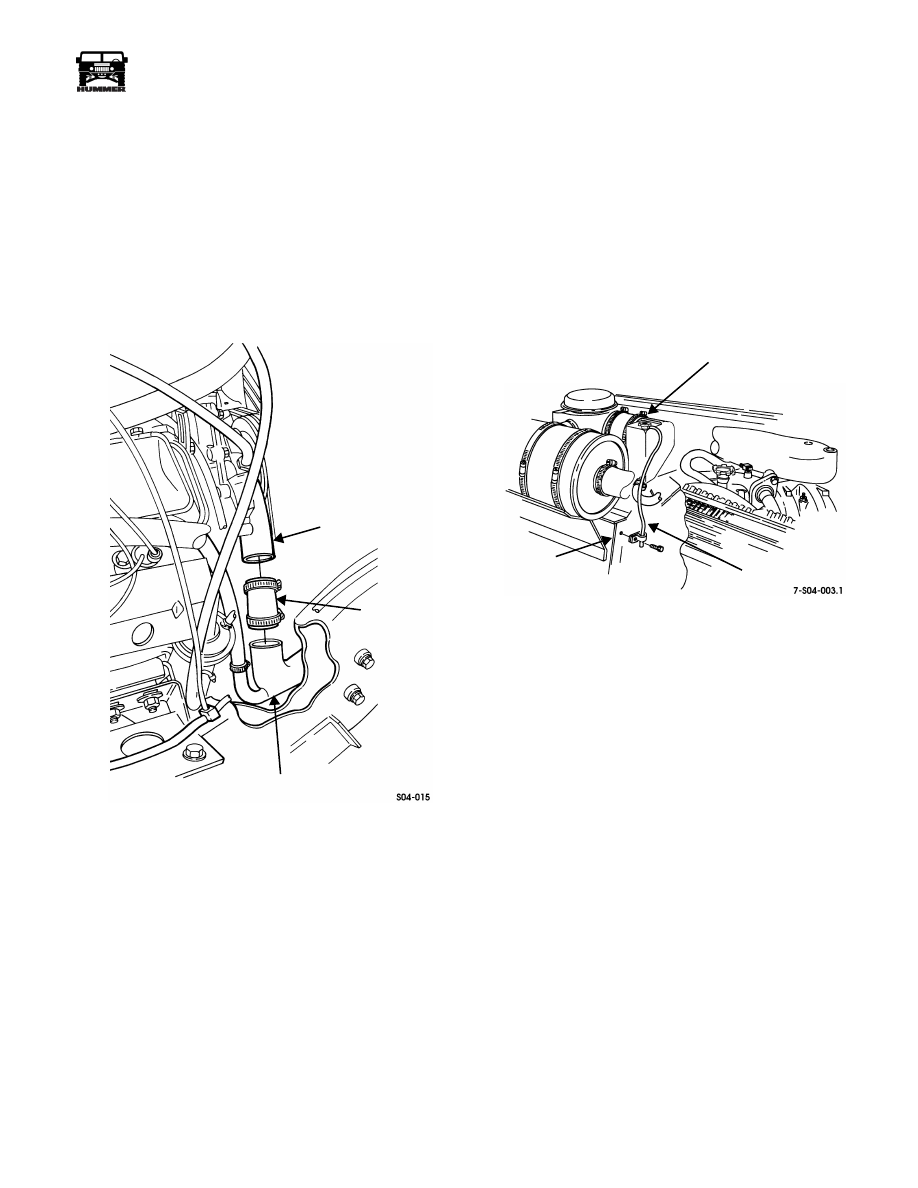
WATER PUMP INLET HOSE REPLACEMENT
Removal
1.
Drain cooling system.
2.
Loosen clamps and remove water pump inlet hose from
water pump and lower tube assembly (Figure 4-18).
Installation
1.
Connect water pump inlet hose to lower tube assembly and
water pump and tighten clamps (Figure 4-18).
2.
Fill cooling system.
Figure 4-18: Water Pump Inlet Hose Location
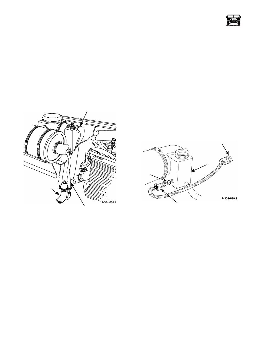
SURGE TANK OVERFLOW HOSE
REPLACEMENT
Removal
1.
Remove overflow hose from surge tank filler neck
(Figure 4-19).
2.
Remove screw, clamp, and overflow hose from body.
Installation
1.
Connect overflow hose to surge tank filler neck (Figure 4-19).
2.
Secure overflow hose to body with clamp and screw.
Figure 4-19: Surge Tank Overflow Hose Mounting
WATER PUMP
WATER PUMP
INLET HOSE
LOWER
TUBE ASSEMBLY
BODY
SURGE TANK FILLER NECK
OVERFLOW
HOSE
4-12
Cooling System
__________________________________________________________
®
SURGE TANK-TO-LOWER RADIATOR TUBE
HOSE REPLACEMENT
Removal
1.
Drain cooling system.
2.
Loosen clamps and remove hose from surge tank and
lower tube assembly (Figure 4-20).
Installation
1.
Install hose on lower tube assembly and surge tank and
tighten clamps (Figure 4-20).
2.
Fill cooling system.
Figure 4-20: Surge Tank-to-Lower Tube Assembly
Hose Location
LOW COOLANT SENSOR
The coolant level sensor is a solid-state semi-conductor device.
The sensor’s resistance varies as a function of its temperature.
As voltage/current flows through the sensor, sensor tempera-
ture increases. In the presence of a liquid, in this case engine
coolant, the temperature of the sensor is controlled by transfer-
ring heat to the coolant. Should the coolant level drop below
the sensor, the heat and resistance of the sensor will rise. The
“Low Coolant” warning light will then illuminate in response
to the increased resistance at the sensor.
Removal
1.
Drain and collect coolant from surge tank.
2.
Disconnect the low coolant sensor electrical connector
from the engine harness connector.
3.
Remove the sensor and O-ring from the surge tank
(Figure 4-21)
Figure 4-21: Low Coolant Sensor
Installation
1.
Position O-ring on sensor and thread sensor into surge
tank (Figure 4-21).
2.
Plug the low coolant sensor electrical connector into the
engine harness connector
3.
Fill surge tank with coolant.
SURGE TANK
LOWER
TUBE ASSEMBLY
SURGE TANK-TO-LOWER TUBE
ASSEMBLY HOSE
SURGE
ELECTRICAL
LOW
O-RING
CONNECTOR
COOLANT
SENSOR
TANK
_________________________________________________________
Cooling System 4-13
®
05745159
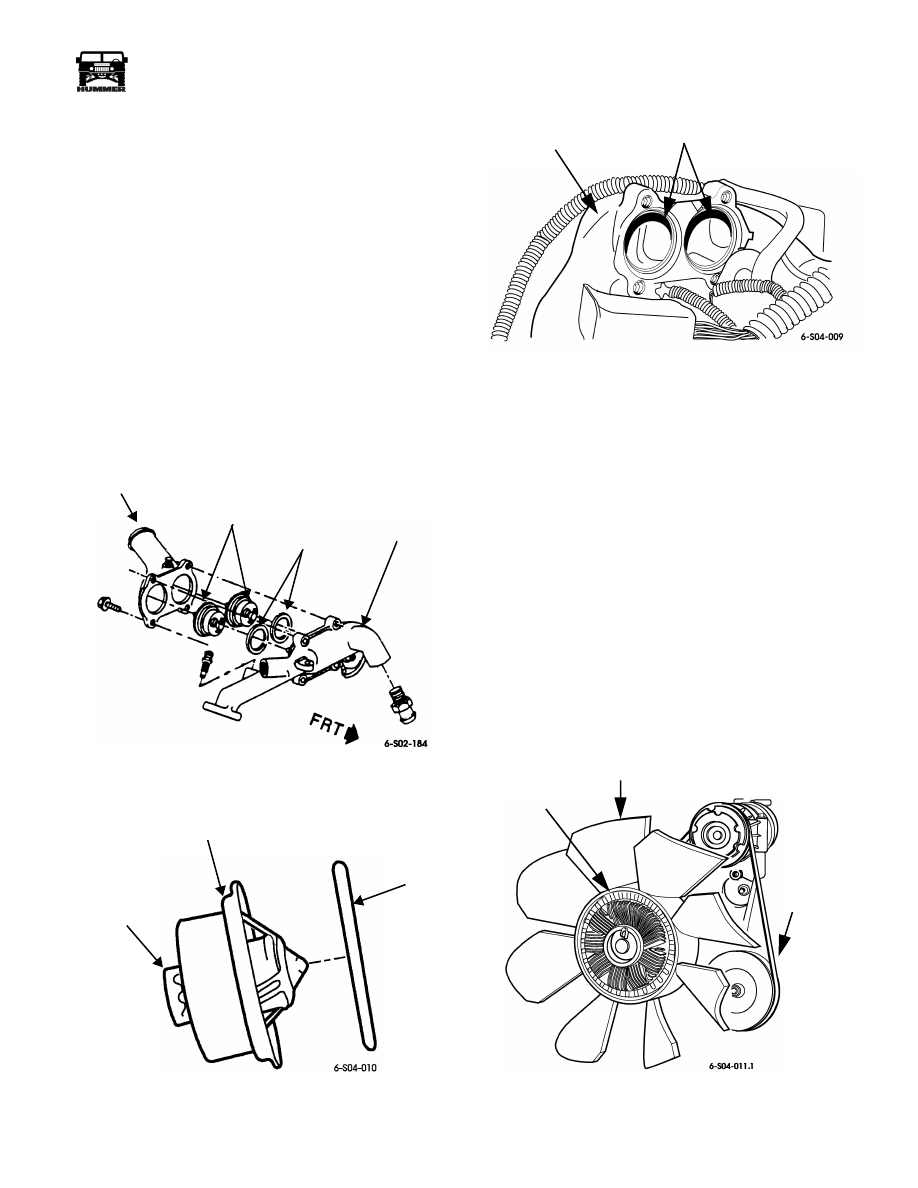
THERMOSTAT REPLACEMENT
1.
Drain engine coolant below level of water crossover.
2.
Remove bolts attaching thermostat cover to crossover
housing.
3.
Remove thermostat cover and gasket (Figure 4-22).
4.
Remove both thermostats (Figure 4-23).
5.
Position new thermostats in crossover housing
(Figure 4-24). Be sure thermostat seals are seated in
counterbores. Wax pellet end of each thermostat goes
toward engine.
6.
Apply Permatex no. 2 to both sides of thermostat housing
gasket. If gasket is not used, apply 3/16 in. (5 mm) bead of
Loctite 599, or Permatex Ultra Copper, or Ultra Black to
cover or crossover mounting surface.
7.
Install thermostat cover and tighten cover bolts securely.
8.
Fill and bleed cooling system.
Figure 4-22: Thermostat and Cover
Removal and Installation
Figure 4-23: Turbo Diesel Thermostat
Figure 4-24: Thermostat Location in Crossover
WATER PUMP AND ADAPTER PLATE
Removal
1.
Remove hood with aid of helper.
2.
Drain engine coolant.
3.
Discharge A/C system refrigerant with equipment set on
recovery mode.
4.
Remove radiator, shroud, coolers, and A/C condenser as
assembly.
5.
Loosen and remove serpentine drive belt.
6.
Remove fan and fan clutch (Figure 4-25).
7.
Disconnect hoses at water pump.
8.
Remove water pump and backing plate attaching bolts/
studs and remove pump and plate as assembly
(Figure 4-26).
9.
Remove water pump and gasket from plate (Figure 4-27).
10. Clean all gasket material and sealer from plate.
Figure 4-25: Fan and Clutch Mounting
THERMOSTAT
HOUSING
TWIN
GASKETS
WATER
CROSSOVER
THERMOSTATS
WAX PELLET
THERMOSTAT
SEAL
WATER
CROSSOVER
THERMOSTAT SEATS
AND COUNTER BORES
FAN CLUTCH
8-BLADE FAN
SERPENTINE
DRIVE BELT

4-14
Cooling System
__________________________________________________________
®
Installation
1.
If new pump is being installed, transfer hose adapter fit-
tings to new pump. Apply Loctite PST to fitting threads
beforehand.
2.
Apply coat of Permatex no. 2, Ultra Black, or Ultra
Copper to each side of water pump gasket. Then position
gasket on pump.
3.
Apply 1/8 - 3/16 in. (3.3-5 mm) wide bead of sealer to
backing plate (Figure 4-28). Encircle bolt hole at bottom
of plate with sealer as shown. Also apply sealer to threads
of bolt or stud used in this hole to avoid leaks.
4.
Install adapter plate and water pump on front cover.
Tighten all studs and short bolts marked A to 13-20 lb-ft
(18-27 N•m). Tighten large studs and large bolt marked B
to 25-37 lb-ft (34-50 N•m) (Figure 4-26).
5.
Attach hoses to water pump.
6.
Install fan and clutch.
7.
Install and adjust serpentine drive belt.
8.
Install radiator, shroud, coolers, and A/C condenser as
assembly.
9.
Evacuate and recharge A/C system.
10. Refill engine cooling system.
11. Install hood.
12. Start engine, bleed air from cooling system, and top off
coolant level.
Figure 4-26: Water Pump and Adapter Plate Removal/Installation
Figure 4-27: Water Pump
ADAPTER PLATE
FRONT
COVER
WATER PUMP
A
A
B
B
A
BYPASS ADAPTER
WATER PUMP
GASKET
BACKING PLATE
Нет комментариевНе стесняйтесь поделиться с нами вашим ценным мнением.
Текст