Hummer H1 (2002+). Manual — part 63

____________________________________________
Transmission/Transfer Case 5-51
®
05745159
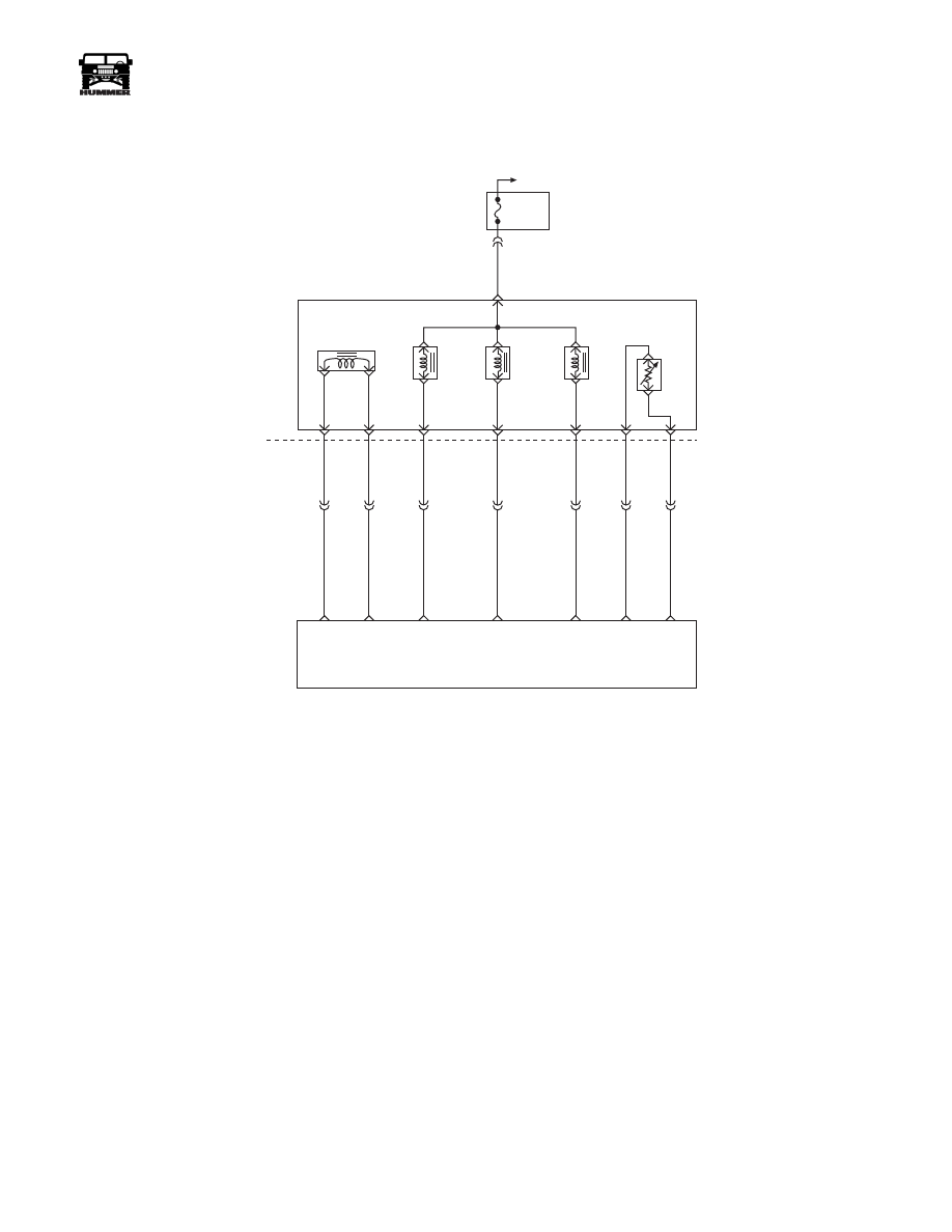
DTC P0560 System Voltage Fault
Circuit Description
Circuit 239 is the voltage feed for the PCM. Circuit 537 is the
battery feed for the PCM.
This DTC detects a low voltage, a high voltage for a long time,
or a high voltage for a short time. This is a type “D” DTC.
Conditions For Setting DTC
System Voltage Low:
• Engine speed is greater than 1500 rpm.
• System voltage is less than 10.5 volts at a maximum
transmission temperature of 152° C (305° F).
• System voltage is less than 6.7 volts at a minimum
transmission temperature of -40° C (-40° F).
• All conditions met for 4 seconds.
System Voltage High:
• System voltage is greater than 19 volts for 4 seconds.
Action Taken When DTC Sets
• The PCM will cause an immediate shift to second gear.
• The PCM will turn off Pressure Control Solenoid.
• The PCM will inhibit converter clutch engagement.
• The PCM will freeze shift adapts.
• The PCM will NOT illuminate the Engine/Trans light.
Conditions For Clearing DTC
• The DTC can be cleared using the scan tool. The DTC
will be cleared when the vehicle has achieved 40 warm-
up cycles without a failure reported.
• The PCM will cancel the DTC default actions when the
fault no longer exists and the ignition is cycled “off”
long enough to power down the PCM.
Diagnostic Aids
• Charging the battery with a battery charger and jump
starting an engine may set DTC(s). If DTC(s) set when
an accessory is operated, check for faulty connections or
excessive current draw.
• Check for loose/damaged terminals at generator.
• Check belt wear/tension.
• If any engine DTCs are present diagnose and clear these
DTCs first. Then check to see if the transmission DTCs
have set.
Test Description
The numbers below refer to the step numbers on the diagnostic
chart.
3.
This test checks charging system voltage.
4.
This test checks battery voltage Input at the PCM.
6.
This test checks ignition voltage input at the PCM.
FUSE 2D
20 AMP
INTERIOR
STS
LAMP
MIL
LAMP
FUSE 3A
20 AMP
EXTERIOR
HOT AT
ALL TIMES
HOT IN RUN
AND START
HOT IN RUN
AND START
FUSE 4B
5 AMP
INTERIOR
G2
G4
FUSE 1H
5 AMP
INTERIOR
DLC
POWERTRAIN
CONTROL
MODULE
SERIAL DATA
CLASS II
MIL
CONTROL
STS LAMP
CONTROL
914 PP
16
4
2
59 BK
C28-C8
570 BK
C28-D7
C28-D6
GROUND
GROUND
570 BK
BATT
BATT
IGN
IGN
C28-C13
C28-D13
C28-C12
C28-C11
C28-D11
TO
C29-B3
537 OR
239 PK
C1-10
C10-J
C10-H
C10-C
C3-G5
C3-F3
C1-25
C1-28
C28-C14
658 BR
714 RD
STATUS
CENTER
HOT AT
ALL TIMES
9-S12-064
554 GRY
30
GR
Y
3-1-01

5-52
Transmission/Transfer Case
_____________________________________________
®
DTC P0560 System Voltage Fault
Step
Action
Value
Yes
No
1
1.
Connect scan tool.
2.
Turn the ignition switch to “on” position.
Important
: Before clearing DTC(s), use the scan tool to record
“Failure Records” for reference, as data will be lost when the
“Clear Info” function is used.
3.
Record the DTC “Failure Records.”
NOTE:
If any other DTCs are present, Refer to applicable diagnostic charts be-
fore continuing.
4.
Using multimeter, measure the battery voltage across the battery terminals.
Record the measurement for future reference.
Is voltage higher than value shown?
10.5
volts
Go to
Step 2
Check
Battery
2
Start the engine and warm to normal operating temperature.
Is generator charging (see voltmeter)?
12-14
volts
Check
charging
system
Go to
Step 4
3
1.
Increase engine speed to 1500 rpm.
2.
Observe scan tool system voltage.
Is system voltage within specified range?
13-15
volts
Go to
Step 4
Check
charging
system
4
1.
Turn the ignition switch “off.”
2.
Disconnect PCM connector (additional DTCs will set).
3.
With engine “off,” turn the ignition switch “on.”
4.
Using the multimeter and Connector Test Adapter Kit, measure the battery
voltage input at PCM connector terminal “J3-C13.”
Is there a voltage variance between the voltage measured at the battery (taken in
Step 2) and at terminal “J3-C13” that is greater than the value shown?
0.5
volts
Go to
Step 5
Go to
Step 5
5
Repair high resistance condition in.
Was the circuit repaired?
—
Go to
Step 10
—
6
1.
Disconnect PCM connector.
2.
Measure ignition voltage input at PCM connector terminals.
Is there a voltage variance between voltage measured at the battery (taken in
Step 2) and at terminal that is greater than value shown?
0.5
volts
Go to
Step 7
Go to
Step 8
7
Repair high resistance condition in circuit 439.
Was the circuit repaired?
—
Go to
Step 10
—
8
Check PCM connector terminals for bent, damaged, or backed out connector
pins. Also check for weak terminal tension.
Was a problem found?
—
Go to
Step 10
Go to
Step 9
9
Replace PCM.
Is replacement complete?
Go to
Step 11
—
10
1.
After the repair is complete, use the scan tool to select “DTC,” then Unclear
Info” function.
2.
Select Specific DTC” and enter DTC “P0560.”
3.
Operate the vehicle under the following conditions:
• Start the vehicle and warm to normal operating temperature. The PCM
must see a system voltage between 8.3 and 18.9 volts.
—
—
—
____________________________________________
Transmission/Transfer Case 5-53
®
05745159
DTC P0711 Transmission Fluid Temperature
Sensor Circuit Range/Performance
Circuit Description
The Automatic Transmission Fluid Temperature (TFT) Sensor
is a thermistor (temperature sensitive resistor). The TFT Sen-
sor is part of the 4L80-E Automatic Transmission Wiring Har-
ness Assembly (A/T Wiring Harness Assembly). The TFT
Sensor receives a 5-volt reference signal from the Powertrain
Control Module (PCM) on circuit 1227. When the fluid tem-
perature is low, the TFT Sensor has a high resistance and the
PCM detects a high voltage on circuit 1227. As fluid tempera-
ture rises, the TFT Sensor resistance gradually decreases and
the PCM senses a lower voltage on circuit 1227.
If the PCM detects no change in the TFT sensor resistance or
unrealistic changes in a short amount of time in the TFT sensor
resistance (multiple changes within seconds), then DTC P0711
sets. DTC P0711 is a type D DTC. For California emissions
vehicles, DTC P0711 is a type B DTC.
FUSE 2A
10A
EXTERIOR
C33-F
351 PK
C34
D
C
S
B
A
M
L
C32-G
C32-F
C32-E
C32-D
C32-C
C32-J
C32-H
C34-E
C27-C15
C27-C7
C28-C5
C28-C6
C28-C4
C29-B12
C27-C9
265 LB
264 RD
924 TN
315 YL
237 LG
359 BK
923 BR
PRESSURE
CONTROL
SOLENOID
(PCS)
TORQUE
CONVERTER
CLUTCH
SOLENOID
(TCC)
1-2 SHIFT
SOLENOID
(1-2)
2-3 SHIFT
SOLENOID
(2-3)
TRANSMISSION
FLUID
TEMPERATURE
SENSOR
(TFT)
PCS
LOW
PCS
HIGH
TCC PWM
SOLENOID
CONTROL
2-3 SS
CONTROL
1-2 SS
CONTROL
SENSOR
GROUND
TFT
SENSOR
SIGNAL
POWERTRAIN
CONTROL
MODULE
(PCM)
HOT IN RUN
AND START
9-S12-071
5-54
Transmission/Transfer Case
_____________________________________________
®
Conditions For Setting The DTC
• No DTCs P1117 or P1118.
• No OSS sensor DTC P0502.
• No A/T ISS sensor. DTC P0716 or P0717.
• No A/T Component Slipping DTC P1870.
• The system voltage is 10.0 - 16.0 volts.
• The engine is running greater than 475 rpm for at least
30 seconds.
• The engine coolant temperature (ECT) is greater than
176° F (80° C).
• The TFT is -40 to +70° F (-40 to + 21 ° C) at start up.
• The ECT has changed at least 122° F (50 ° C) since start
up.
• The vehicle speed is greater than 3 mph for at least 900
seconds (15 minutes).
• The TCC slip speed is greater than 60 rpm for at least
850 seconds (14 minutes)>
• DTC P0711 sets if all of the above conditions have been
met and one of the following conditions exist:
- Non TFT change: The TFT has not changed more
than 4° F (2.25° C), in more than 80 seconds.
- An unrealistic temperature change: The TFT has
changed more than 68°F (20 ° C) 14 times in 7 sec-
onds.
Action Taken When The DTC Sets
• The PCM uses a TFT default value of 280° F (140° C).
• The PCM freezes shift adapts.
• The PCM illuminates the Malfunction Indicator Lamp
(MIL).
Conditions For Clearing The MIL/DTC
• For California Emissions only, the PCM turns off the
MIL after three consecutive ignition cycles without a
failure report.
• The DTC can be cleared using the scan tool. The DTC
will be cleared when the vehicle has achieved 40 warm-
up cycles without a failure reported.
• The PCM will cancel the DTC default actions when the
fault no longer exists and the ignition is OFF long
enough to power down the PCM.
Diagnostic Aids
• When diagnosing for a possible intermittent short or
open condition, wiggle the wiring harness while observ-
ing test equipment for a change.
• If any engine DTCs are present diagnose and clear these
DTCs first. Then check to see if the transmission DTCs
have reset.
Test Description
• The numbers below refer to the step numbers on the di-
agnostic chart.
2. This step tests for proper A/T fluid level and condition.
3. This step verifies that the vehicle sets DTC P0711.
5. The 12-volt test lamp is used as a fixed resistance.
6. Perform this step in order to ensure that the PCM monitors
circuit 1227.
8. The TFT Sensor is part of the A/T Wiring Harness Assem-
bly
Нет комментариевНе стесняйтесь поделиться с нами вашим ценным мнением.
Текст