Hummer H1 (2002+). Manual — part 64

____________________________________________
Transmission/Transfer Case 5-55
®
05745159
DTC P0711 Transmission Fluid Temperature Sensor Circuit Range/Performance
Step
Action
Value
Yes
No
1
Was the Powertrain ON-Board Diagnostic (OBD) System
Check performed?
—
Go to Step 2
Go to Powertrain OBD
System Check
2
Perform the A/T Fluid Checking Procedure.
Did you perform the fluid checking procedure?
—
Go to Step 3
Go to Transmission
Fluid Checking Proce-
dure.
3
1.
Install the scan tool (Tech 1).
2.
With the engine OFF, turn the ignition switch to the
RUN position.
Important
: Before clearing the DTC’s, use the scan tool in
order to record the Freeze Frame and Failure Records for
reference. The Clear Info function will erase the stored data.
3.
Record the DTC Freeze Frame and Failure Records.
4.
Select Trans. Fluid Temp on the scan tool.
5.
Drive the vehicle and observe the scan tool for one of
the following conditions:
• No TFT change
• An unrealistic change (The TFT change is greater
than 36° F (20° C) 14 times in 7 seconds).
Did either of the fail conditions occur?
—
Go to Step 4
Fault not present at this
time. Refer to Diagnos-
tic Aids.
4
Did the scan tool display an unrealistic change condition?
—
Go to Step 6
Go to Step 5
5
1.
Turn the ignition switch OFF.
6.
Disconnect the transmission 20-way connector.
7.
Install a 12 volt test lamp between terminal L and
terminal M of the engine side of the transmission 20-
way connector. Use the J– 35616-A Connector Test
Adapter Kit (Covered in Electrical Section 12)
8.
Turn the ignition switch to the RUN position.
Does the scan tool Trans. Fluid Temp. display an unrealistic
change?
—
Go to Step 7
Go to Step 8
6
1.
Record the scan tool TFT display from step 4.
2.
Turn the ignition OFF.
3.
Disconnect the transmission 20-way connector.
4.
Turn the ignition switch to the RUN position.
Is the scan tool Trans. Fluid Temp. the same as in step 4?
—
Go to Step 7
Go to Step 8
7
Replace the PCM. Refer to Section 2.
Is the replacement complete?
—
Go to Step 9
—
8
Replace the A/T Wiring Harness Assembly. Refer to 4L80-E
Automatic Transmission ON-Vehicle Service.
Is the replacement complete?
—
Go to Step 9
—

5-56
Transmission/Transfer Case
_____________________________________________
®
9
In order to verify your repair, perform the following proce-
dure:
1.
Select DTC.
2.
Select Clear Info.
3.
Operate the vehicle under the following conditions:
• The TFT changes by more than 3° C (5° F) after the
engine has been running for 35 seconds.
• For a period of at least 11 seconds, the TFT does not
change more than 36° F (20° C) within 0.2 seconds.
4.
Select Specific DTC.
5.
Enter DTC P0711.
Has the test run and passed?
—
System OK
Begin the diagnosis
again. Go to Step 1.
DTC P0711 Transmission Fluid Temperature Sensor Circuit Range/Performance (Cont’d)
Step
Action
Value
Yes
No
____________________________________________
Transmission/Transfer Case 5-57
®
05745159
DTC P0712 Transmission Fluid Temperature
(TFT) Sensor Circuit - Low Input
(High Temperature Indicated)
Circuit Description
The transmission fluid temperature (TFT) sensor is a ther-
mister that controls signal voltage to the PCM. The PCM sup-
plies a 5-volt reference signal to the sensor. When the
transmission fluid is cold, sensor resistance is high. The PCM
detects high signal voltage. As the transmission fluid tempera-
ture increases to the normal operating temperature of 100° C
(212° F), the sensor resistance becomes less and the voltage
decreases to 1.5 to 2 volts.
This DTC detects a continuous short to ground in the tempera-
ture signal circuit or the sensor itself.
Conditions For Setting The DTC
• Ignition is “on.”
• TFT sensor indicating a voltage less than 0.3 volts.
• All conditions met for 10 seconds.
Action Taken When The DTC Sets
• Transmission default temperature will be 140° C (275° F).
NOTE:
Scan tool will not display default temperature.
• The PCM will illuminate the warning light.
Conditions For Clearing The DTC
• The PCM will turn off the warning light after three con-
secutive ignition cycles without a failure reported.
• The DTC can be cleared using the scan tool. The DTC
will be when the vehicle has achieved 40 warm-up cy-
cles without a failure reported.
• The PCM will cancel the DTC default actions when the
fault no longer exists and the ignition is cycled “off”
long enough to power down the PCM.
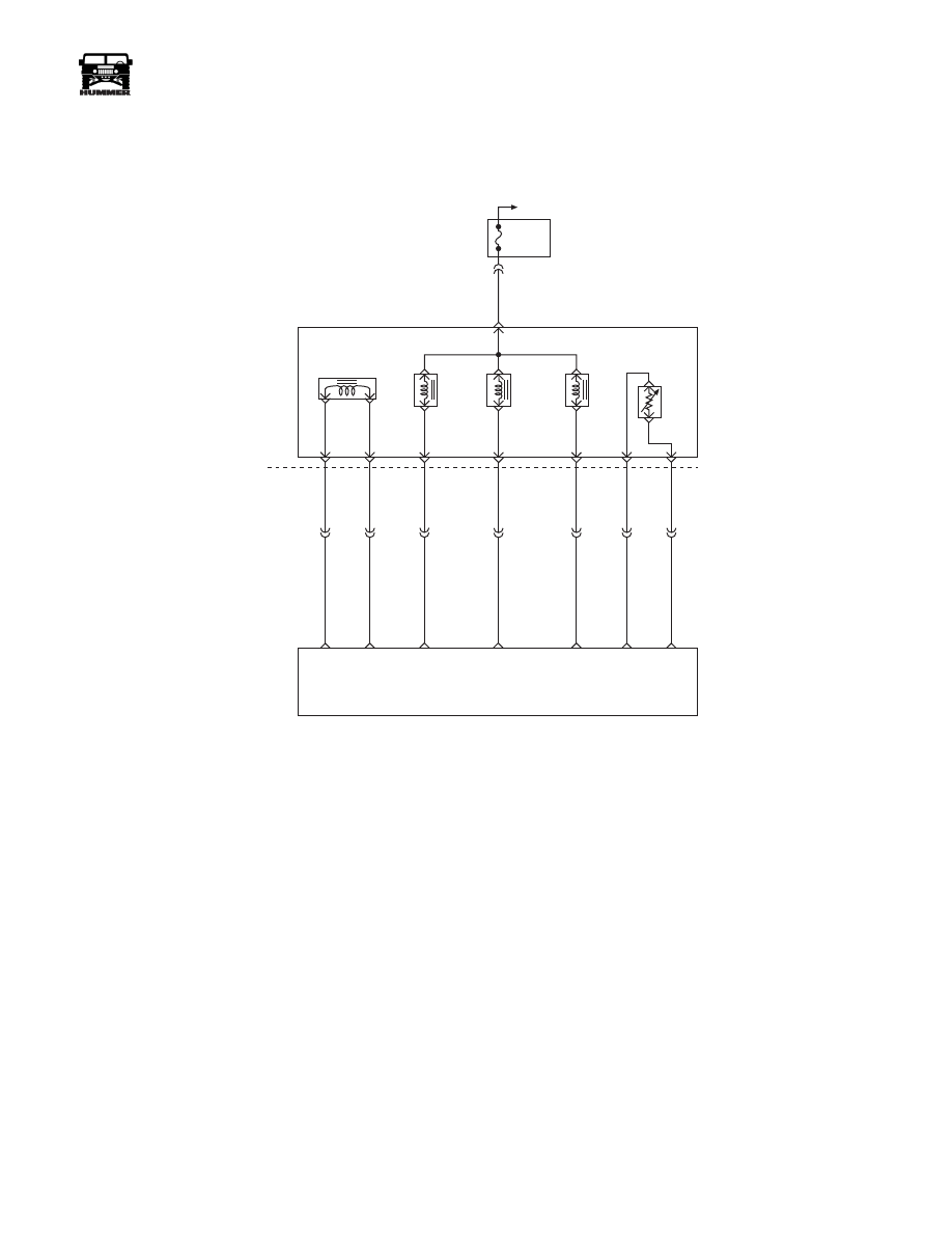
FUSE 2A
10A
EXTERIOR
C33-F
351 PK
C34
D
C
S
B
A
M
L
C32-G
C32-F
C32-E
C32-D
C32-C
C32-J
C32-H
C34-E
C27-C15
C27-C7
C28-C5
C28-C6
C28-C4
C29-B12
C27-C9
265 LB
264 RD
924 TN
315 YL
237 LG
359 BK
923 BR
PRESSURE
CONTROL
SOLENOID
(PCS)
TORQUE
CONVERTER
CLUTCH
SOLENOID
(TCC)
1-2 SHIFT
SOLENOID
(1-2)
2-3 SHIFT
SOLENOID
(2-3)
TRANSMISSION
FLUID
TEMPERATURE
SENSOR
(TFT)
PCS
LOW
PCS
HIGH
TCC PWM
SOLENOID
CONTROL
2-3 SS
CONTROL
1-2 SS
CONTROL
SENSOR
GROUND
TFT
SENSOR
SIGNAL
POWERTRAIN
CONTROL
MODULE
(PCM)
HOT IN RUN
AND START
5-58
Transmission/Transfer Case
_____________________________________________
®
Diagnostic Aids
• With a transmission fluid overtemperature DTC P1812
also set, check the transmission cooling system.
• Check harness routing for a potential short to ground in
circuit. Scan tool TFT display should rise steadily to
about 100° C (212° F), then stabilize.
• Inspect the wiring for poor electrical connections at the
PCM and at the transmission 20-way connector. Look for
possible bent, backed out, deformed or damaged termi-
nals. Check for weak terminal tension as well. Also check
for a chafed wire that could short to bare metal or other
wiring. Inspect for a broken wire inside the insulation.
• When diagnosing for a possible intermittent short or
open condition, wriggle the wiring harness while ob-
serving test equipment for a change.
• The temperature to resistance value scale may be used
to test the sensor at various temperature levels to evalu-
ate the possibility of a “skewed” (mis-scaled) sensor. A
“skewed” sensor could result in garage shifts or con-
verter clutch complaints.
• Verify customer driving habits, trailer towing, etc...
• If any engine DTCs or TP Sensor codes are present di-
agnose and clear these DTCs first. Then check to see if
the transmission DTCs have reset.
Test Description
The numbers below refer to the step numbers on the diagnostic
chart.
2.This test checks for a short to ground or a “skewed” sen-
sor.
3.This test checks for an internal fault within the transmis-
sion by creating an open.
Нет комментариевНе стесняйтесь поделиться с нами вашим ценным мнением.
Текст