Hummer H1 (2002+). Manual — part 290
_____________________________________________________
PCM/Tech 1 Scan Tool 93
®
05745159
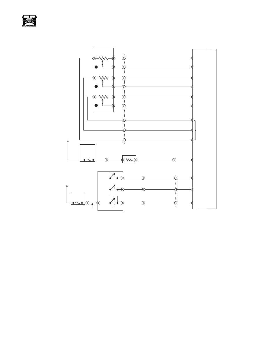
DTC P0568 Cruise Set Circuit
Circuit Description
The cruise Set/Coast switch is an input to the fuel control por-
tion of the PCM. These inputs allow the PCM to control and
hold a requested speed. Cruise Set/Coast switch sends an igni-
tion voltage signal to the PCM when the Set/Coast switch is
“ON”. This is a type D DTC.
Conditions for Setting the DTC
• Cruise switch “OFF”.
• Ignition voltage on Set switch signal circuit.
or
• Cruise switch “ON”.
• Set switch “ON” for longer than 25.5 seconds
Action Taken When the DTC Sets
• The PCM will disallow all cruise inputs.
• TCC shift schedules may be affected.
Conditions for Clearing the MIL/DTC
• A History DTC will clear when forty consecutive
warm-up cycles that the diagnostic does not fail (coolant
temperature has risen 5°C (40°F) from start up coolant
temperature and engine coolant temperature exceeds
71°C (160°F) that same ignition cycle).
• Use of a Scan Tool.
Diagnostic Aids
If the Set/Coast switch stuck in the “ON” position or the driver
is holding the Set/Coast switch “ON” for longer than 25.5 sec-
onds, DTC P0569 will set. DTC P0568 only checks the signal
circuit for a short to voltage.
Test Description
Number(s) below refer to the number(s) on the diagnostic ta-
ble.
2. This step determines if the signal circuit is shorted to volt-
age.
FUSE 5C
10AMP
INTERIOR
FUSE 3A
10 AMP
EXTERIOR
ON/
OFF
SET
COAST
RESUME
ACCEL
HOT IN RUN
AND START
HOT IN RUN
AND START
A
29
42
37
C1
C29-A11
C29-B11
C27-D10
C28-D14
C28-C2
C27-D12
C27-D3
C27-D4
C27-D6
C29-B2
C29-B1
C27-C5
C29-A12
C5-D3
C5-A4
A
B
154 TN
151 GY
152 DB
153 LG
ON / OFF
SIGNAL
SET
COAST
SIGNAL
RESUME
ACCEL
SIGNAL
WASTEGATE
SOLENOID
CONTROL
5 VOLT
REFERENCE
APP 3
SIGNAL
GROUND
APP 1
SIGNAL
GROUND
GROUND
D
B
C
A
G
E
F
J
K
3
1
2
C1
22
20
14
15
60
32
53
17
44
720 TN
717 WH
723 YL
724 DG
725 GY
718 DB
719 BR
721 LB
722 PP
ACCELERATIOR
PEDAL POSITION
SENSOR
POWERTRAIN
CONTROL
MODULE
(PCM)
APP 2
SIGNAL
9-S12-055
B
C
D
295 BR
YL
GRN
RD

94
PCM/Tech 1 Scan Tool
_____________________________________________________
®
3. This step determines if the PCM or switch is at fault.
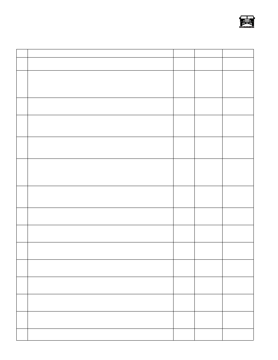
DTC P0568 - Cruise Set Circuit
Step
Action
Value(s)
Yes
No
1
Important:
Before clearing DTC(s) use the scan tool “Capture Info” to
record freeze frame and failure records for reference, as data will be lost
when “Clear Info” function is used.
Was the “On-Board Diagnostic (OBD) System Check” performed?
—
Go to Step 2.
Go to OBD
System Check.
2
1. Scan tool connected.
2. Ignition “ON”, engine “OFF”.
3. Cruise switch “OFF”.
Does scan tool display Set switch “ON”?
—
Go to Step 3.
Go to Step 4.
3
1. Ignition “ON”.
2. Disconnect the PCM brown 24 way connector.
3. Probe the Set switch signal circuit at the PCM harness with a test light
connected to chassis ground.
Is the test light “ON”?
—
Go to Step 5.
Go to Step 7.
4
DTC is intermittent. If no additional DTCs are stored, refer to “Diagnostic
Aids”. If additional DTCs are stored, refer to those charts(s) first.
Are additional DTCs stored?
—
Go to the
applicable
DTC table
Go to
Diagnostic
Aids
5
1. Resume switch signal circuit is shorted to voltage.
2. Repair as necessary.
Is action complete?
—
Go to Step 8.
—
6
Replace the faulty PCM. Notice: If the PCM is faulty, the new PCM must
be programmed. Go to PCM replacement and programming procedures.
Is the action complete?
—
Go to Step 7.
—
7
1. Using the Scan Tool, select “DTC”, “Clear Info”.
2. Start engine and idle at normal operating temperature.
3. Select “DTC”, “Specific”, then enter the DTC number which was set.
4. Operate vehicle within the conditions for setting this DTC as specified
in the supporting text.
Does the Scan Tool indicate that this diagnostic Ran and Passed?
—
Go to Step 8.
Go to Step 2.
8
Using the Scan Tool, select “Capture Info”, “Review Info”.
Are any DTCs displayed that have not been diagnosed?
—
Go to the
applicable
DTC table
System OK.
_____________________________________________________
PCM/Tech 1 Scan Tool 95
®
05745159
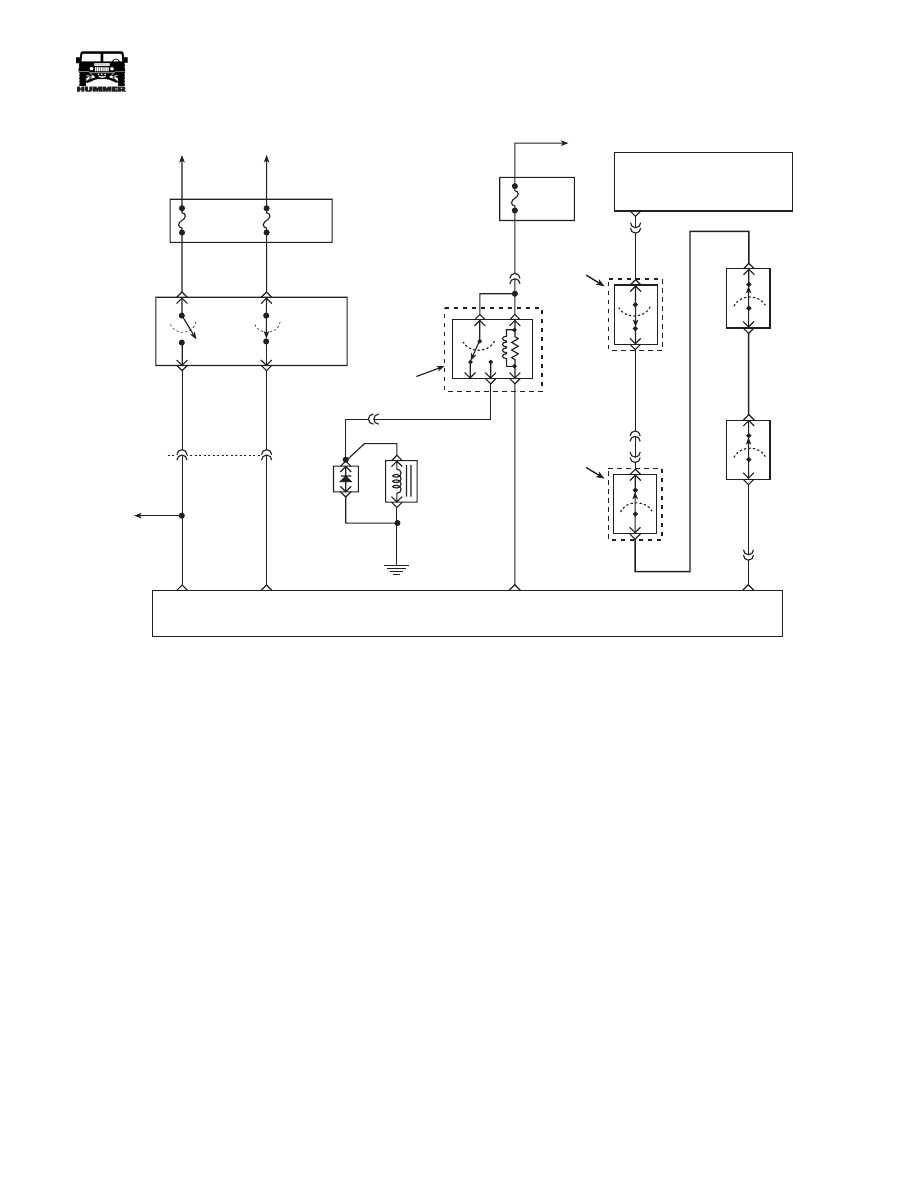
DTC P0571 Cruise Brake Switch Circuit
Circuit Description
The TCC normally closed brake switch supplies a B+ signal on
CKT 810 to the PCM. The circuit is opened when the brakes
are applied. The stop lamp/cruise control normally open brake
switch supplies a B+ signal on CKT 22 to the PCM when the
brake is applied. This is a type D DTC.
Conditions for Setting the DTC
• Switches disagree for 10 consecutive minutes.
or
• TCC and cruise control brake switches are not toggling
“open” and “closed” during 6 brake applications on
same ignition cycle.
Action Taken When the DTC Sets
Fourth gear operation in hot mode, and cruise control opera-
tion.
Conditions for Clearing the MIL/DTC
• A History DTC will clear when forty consecutive
warm-up cycles that the diagnostic does not fail (coolant
temperature has risen 5°C (40°F) from start up coolant
temperature and engine coolant temperature exceeds
71°C (160°F) that same ignition cycle).
• Use of a scan.
Diagnostic Aids
Refer to PCM Intermittent Diagnostic Trouble Codes or Per-
formance. Check customer driving habits and/or unusual traf-
fic conditions (i.e. stop and go, expressway traffic).
Test Description
Number(s) below refer to the number(s) on the diagnostic ta-
ble.
3. This test simulates brake switch closed or brakes “OFF”.
4. This test checks the feed circuit.
FUSE 4D
15 AMP
INTERIOR
FUSE 6B
5 AMP
INTERIOR
HOT AT
ALL TIMES
HOT IN RUN
AND START
STOP LAMP
SWITCH
TCC CRUISE
BRAKE SWITCH
A
D
B
C
TO
STOP
LAMPS
C1
31
40
10 OR
291 PK
22 RD
810 PP
STOP
LAMP
SIGNAL
TCC/ CRUISE
BRAKE SIGNAL
FUSE 2C
10 AMP
INTERIOR
HOT IN RUN
AND START
C1-1
30
85
87
86
A/C COMPRESSOR
ENABLE
RELAY CONTROL
A/C
COMPRESSOR
CLUTCH
DIODE
C5-8
400 LG
A/C COMPRESSOR
CLUTCH RELAY
EXTERIOR
FUSE
BOX
G1
440 RD
59 BK
348 BR
C28-D5
HVAC
CONTROL
MODULE
C6-J8
H
347 YL
A/C
REQUEST
SIGNAL
TEMPERATURE
CUTOUT
SWITCH
HVAC
UNIT
C1-39
C4-2
198 TN
C4-5
438 OR
439 YL
C27-C2
A/C
REQUEST
SIGNAL
COMPRESSOR
HIGH
PRESSURE
CUTOUT
SWITCH
AMBIENT
TEMP
CUTOUT
SWITCH
LOW
PRESSURE
CUTOUT
SWITCH
9-S12-054
96
PCM/Tech 1 Scan Tool
_____________________________________________________
®
DTC P0571 - Cruise Brake Switch Circuit
Step
Action
Value(s)
Yes
No
1
Important:
Before clearing DTC(s) use the scan tool “Capture Info”
Was the “On-Board Diagnostic (OBD) System Check” performed?
—
Go to Step 2.
Go to OBD
System Check.
2
1. Scan tool installed.
2. Ignition “ON”, engine “OFF”.
3. Apply brakes.
Does scan tool display Cruise Brake switch “Closed” and then “Open” when
brake is released?
—
Go to Step 3.
Go to Step 4.
3
Apply brakes again.
Does scan tool display Brake switch “Closed” and then “Open” when brake is
released?
—
Go to Step 8.
Go to Step 6.
4
1. Ignition “ON”, engine “OFF”.
2. Stop lamp switch disconnected.
3. With test light connected to ground, probe normally open feed circuit (termi-
nal “B”). Is the test light “ON”?
—
Go to Step 5.
Go to Step 9.
5
1. Disconnect stop lamp switch.
2. Jumper normally open (terminal “A”) feed circuit and the normally open sig-
nal circuits (terminal “B”) together.
Does scan tool display Cruise Brake switch “Closed”?
—
Go to Step 6.
Go to Step 10.
6
1. Ignition “ON”, engine “OFF”.
2. Stop lamp switch disconnected.
3. With test light connected to ground, probe normally closed feed circuit (ter-
minal “F”).
Is the test light “ON”?
—
Go to Step 7.
Go to Step 12.
7
1. Stop lamp switch disconnected.
2. Jumper normally closed (terminal “F”) feed circuit and the normally closed
signal circuits (terminal “E”) together.
Does scan tool display Cruise Brake switch “Closed”?
—
Go to Step 6.
Go to Step 14.
8
DTC is intermittent. If no additional DTCs are stored, refer to “Diagnostic
Aids”. If additional DTCs are stored, refer to those charts(s) first.
Are additional DTCs stored?
—
Go to
applicable
DTC table.
Go to
Diagnostic Aids
9
Check normally open signal circuit (terminal “B”) for an open or short to
ground.
Is action complete?
—
Go to Step 17.
—
10
Check normally open Cruise Brake switch signal circuit for an open or short to
ground.
Was a repair performed?
—
Go to Step 17. Go to Step 11.
11
Check normally open Cruise Brake switch signal circuit for a poor connection
at PCM.
Was a repair performed?
—
Go to Step 17. Go to Step 16.
12
Check normally closed feed circuit (terminal “F”) for an open or short to
ground.
Is action complete?
—
Go to Step 17.
—
13
Check normally closed Cruise Brake switch signal circuit for an open or short
to ground.
Was a repair performed?
—
Go to Step 17. Go to Step 14.
14
Check normally closed Cruise Brake switch signal circuit for a poor connection
at PCM.
Is action complete?
—
Go to Step 17.
—
15
Replace stop lamp switch.
Is action complete?
—
Go to Step 17.
—
Нет комментариевНе стесняйтесь поделиться с нами вашим ценным мнением.
Текст