Hummer H1 (2002+). Manual — part 289
_____________________________________________________
PCM/Tech 1 Scan Tool 89
®
05745159
DTC P0501 Vehicle Speed Sensor Circuit
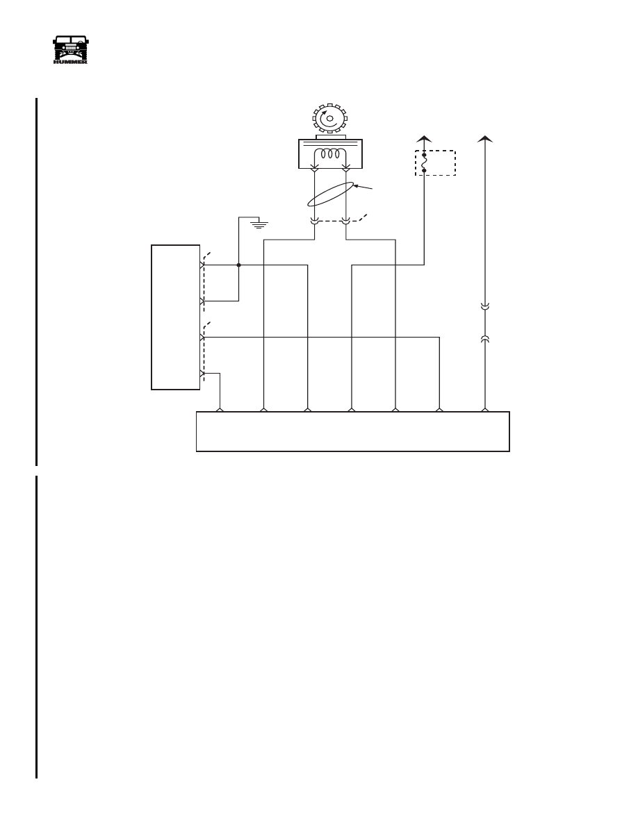
Circuit Description
The speed sensor circuit consists of a magnetic induction type
sensor, a Digital Ratio Adaptor (DRA) and wiring. Geared
teeth pressed on the output shaft induce an alternating current
in the sensor. This A/C signal is transmitted to the DRA. The
DRA compensates for various axle ratios and converts the sig-
nal into a digital signal for use by the speedometer, cruise con-
trol, and the PCM. The DRA sends two different signal to the
PCM. Circuit 565 sends a signal of 40 pulses per revolution of
the output shaft to the PCM. This signal is used to control shift
points, line pressure, TCC and diagnostic codes. Circuit 223
sends a signal of 4000 pulses per mile to the PCM. This signal
is used to control engine operating functions, cruise control
and DTCs.When DTC P0501 or P0723 is set, second gear only at
a maximum line pressure will occur. This is a type D DTC.
Conditions for Setting the DTC
• Vehicle speed greater than 20 m.p.h.
• Four wheel low not selected.
• VSS buffer calculated speed is less than half the trans-
mission calculated speed.
• VSS buffer calculated speed is greater than transmission
calculated speed by 20 m.p.h.
• All conditions met for 2 seconds.
Action Taken When the DTC Sets
No cruise control.
Conditions for Clearing the MIL/DTC
• A History DTC will clear when forty consecutive
warm-up cycles that the diagnostic does not fail (coolant
temperature has risen 5°C (40°F) from start up coolant
temperature and engine coolant temperature exceeds
71°C (160°F) that same ignition cycle).
• Use of a scan.
Diagnostic Aids
Check connections at VSS buffer and PCM. Refer to
4L80EDiagnostic Diagnostic Trouble Codes, Section 10 if
DTC P0722 or DTC P0723 is also set.
Test Description
Number(s) below refer to the number(s) on the diagnostic table.
3. This tests for B+ at VSS buffer.
4. This tests for proper ground path for vehicle speed sensor
signal buffer.
TWISTED
PAIR
VEHICLE
SPEED
SENSOR
(VSS)
B
A
GROUND
VEHICLE
SPEED
SENSOR
RETURN
4
679 LG
VEHICLE
SPEED
DIGITAL RATIO ADAPTER
CRUISE
CONTROL
REFERENCE
SIGNAL
4000 PPM
SPEEDO
REFERENCE
SIGNAL
00-S12-038
+12 VOLT
IGNITION
SIGNAL
OUTPUT SHAFT
REVOLUTION
SIGNAL
7
8
9
12
13
10
A6
570 BK
POWERTRAIN
CONTROL
MODULE
( PCM )
GROUND
GROUND
4000 PPM
CRUISE
CONTROL
REFERENCE
SIGNAL
A7
D6
D9
570 BK
565 BR
C29
C28
FUSE
1D
15 AMP
570 BR
239 PK
676 PP
565 BR
353 YL
G2
TO
IGNITION
EXTERIOR
FUSE
BOX
C1-18
C3-P9
TO
SPEEDO
B
A
C33
223 DB
40 PULSE
OUTPUT SHAFT
REVOLUTION
SIGNAL
TO PCM
3-1-01

90
PCM/Tech 1 Scan Tool
_____________________________________________________
®
DTC P0501 - Vehicle Speed Sensor Circuit
Step
Action
Value(s)
Yes
No
1
Important:
Before clearing DTC(s) use the scan tool “Capture Info” to
record freeze frame and failure records for reference, as data will be lost
when “Clear Info” function is used.
Was the “On-Board Diagnostic (OBD) System Check” performed?
—
Go to Step 2.
Go to OBD
System Check.
2
1. Install scan tool.
2. Raise drive wheels.
3. Engine operating.
4. Transmission in any drive range.
With drive wheels rotating, does vehicle speed increase with drive wheel
speed increase?
—
Go to Step 7.
Go to Step 3.
3
1. Transmission in park.
2. Back probe VSS buffer module ignition feed circuit with a test light con-
nected to ground. Is the test light “ON”?
—
Go to Step 4.
Go to Step 8.
4
Back probe VSS buffer module ignition feed circuit to the ground circuit
with a test light.
Is the test light “ON”?
—
Go to Step 5.
Go to Step 9.
5
1. Back probe VSS buffer module at VSS input circuit (C7) to the other
VSS input circuit (C12) with a J–39200 on the AC scale.
2. Transmission in any drive range with drive wheels rotating.
Does voltage increase on J–39200 with drive wheel increase?
—
Go to Step 6.
Go to Step 10.
6
Does scan tool display a trans output speed (MPH) increase with drive
wheel increase?
—
Go to Step 11. Go to Step 13.
7
DTC is intermittent. If no additional DTCs are stored, refer to “Diagnostic
Aids”. If additional DTCs are stored, refer those charts(s) first.
Are additional DTCs stored?
—
Go to
applicable
DTC table.
Go to
Diagnostic Aids
8
Repair the open in the ignition feed circuit.
Is action complete?
—
Go to Step 15.
—
9
Repair the open in the ground circuit.
Is action complete?
—
Go to Step 15.
—
10
Check the complete VSS input circuit for an open or short to ground.
Was a repair performed?
—
Go to Step 15.
—
11
Check VSS output circuit for an open or short to ground.
Was a repair performed?
—
Go to Step 15. Go to Step 12.
12
Check VSS output circuit for a poor connection at buffer module and PCM.
Was a repair performed?
—
Go to Step 15. Go to Step 14.
13
Replace VSS buffer module.
Is action complete?
—
Go to Step 15.
—
14
Replace the faulty PCM. Notice: If the PCM is faulty, the new PCM must
be programmed. Go to PCM replacement and programming procedures.
Is the action complete?
—
Go to Step 15.
—
15
1. Using the Scan Tool, select “DTC”, “Clear Info”.
2. Start engine and idle at normal operating temperature.
3. Select “DTC”, “Specific”, then enter the DTC number which was set.
4. Operate vehicle within the conditions for setting this DTC as specified in
the supporting text.
Does the Scan Tool indicate that this diagnostic Ran and Passed?
—
Go to Step 16.
Go to Step 2.
16
Using the Scan Tool, select “Capture Info”, “Review Info”.
Are any DTCs displayed that have not been diagnosed?
—
Go to the
DTC table
System OK.
_____________________________________________________
PCM/Tech 1 Scan Tool 91
®
05745159
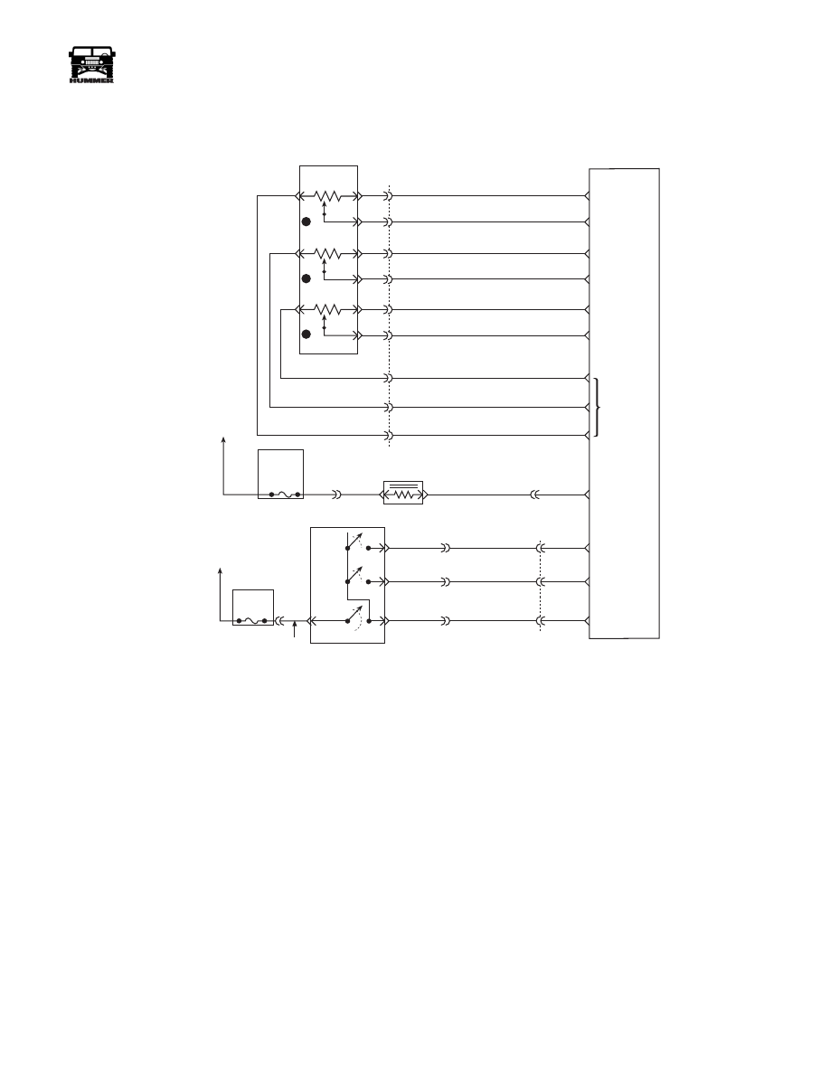
DTC P0567 Cruise Resume Circuit
Circuit Description
The cruise Resume/Accel switch is an input to the fuel control
portion of the PCM. These inputs allow the PCM to control
and hold a requested speed. Cruise Resume/Accel switch sends
ignition voltage to the PCM when the switch is closed (“ON”).
This is a type D DTC.
Conditions for Setting the DTC
• Cruise switch “OFF”.
• Ignition voltage on Resume switch signal circuit.
or
• Cruise switch “ON”.
• Resume switch “ON” for longer than 25.5 seconds
Action Taken When the DTC Sets
• Will not turn on the MIL.
• The PCM will disallow all cruise inputs.
• TCC shift schedules may be affected.
Conditions for Clearing the MIL/DTC
• A History DTC will clear when forty consecutive
warm-up cycles that the diagnostic does not fail (coolant
temperature has risen 5°C (40°F) from start up coolant
temperature and engine coolant temperature exceeds
71°C (160°F) that same ignition cycle).
• Use of a Scan Tool.
Diagnostic Aids
Check for a resume/accel switch stuck in the engage position
or the signal circuit is shorted to voltage.
Test Description
Number(s) below refer to the number(s) on the diagnostic ta-
ble.
2. This step determines if the signal circuit is shorted to volt-
age.
3. This step determines if the PCM or switch is at fault.
FUSE 5C
10AMP
INTERIOR
FUSE 3A
10 AMP
EXTERIOR
ON/
OFF
SET
COAST
RESUME
ACCEL
HOT IN RUN
AND START
HOT IN RUN
AND START
A
29
42
37
C1
C29-A11
C29-B11
C27-D10
C28-D14
C28-C2
C27-D12
C27-D3
C27-D4
C27-D6
C29-B2
C29-B1
C27-C5
C29-A12
C5-D3
C5-A4
A
B
154 TN
151 GY
152 DB
153 LG
ON / OFF
SIGNAL
SET
COAST
SIGNAL
RESUME
ACCEL
SIGNAL
WASTEGATE
SOLENOID
CONTROL
5 VOLT
REFERENCE
APP 3
SIGNAL
GROUND
APP 1
SIGNAL
GROUND
GROUND
D
B
C
A
G
E
F
J
K
3
1
2
C1
22
20
14
15
60
32
53
17
44
720 TN
717 WH
723 YL
724 DG
725 GY
718 DB
719 BR
721 LB
722 PP
ACCELERATIOR
PEDAL POSITION
SENSOR
POWERTRAIN
CONTROL
MODULE
(PCM)
APP 2
SIGNAL
9-S12-055
B
C
D
295 BR
YL
GRN
RD

92
PCM/Tech 1 Scan Tool
_____________________________________________________
®
DTC P0567 - Cruise Resume Circuit
Step
Action
Value(s)
Yes
No
1
Important:
Before clearing DTC(s) use the scan tool “Capture Info” to
record freeze frame and failure records for reference, as data will be lost
when “Clear Info” function is used.
Was the “On-Board Diagnostic (OBD) System Check” performed?
—
Go to Step 2.
Go to OBD
System Check.
2
1. Scan tool connected.
2. Ignition “ON”, engine “OFF”.
3. Cruise switch “OFF”.
Does scan tool display Resume Switch “ON”?
—
Go to Step 3.
Go to Step 4.
3
1. Ignition “ON”.
2. Disconnect the PCM brown 32 way connector.
3. Probe the Resume switch signal circuit at the PCM harness with a test
light connected to chassis ground.
Is the test light “ON”?
—
Go to Step 5.
Go to Step 7.
4
DTC is intermittent. If no additional DTCs are stored, refer to “Diagnostic
Aids”. If additional DTCs are stored, refer to those charts(s) first.
Are additional DTCs stored?
—
Go to the
applicable
DTC table
Go to
Diagnostic
Aids.
5
1. Resume switch signal circuit is shorted to voltage.
2. Repair as necessary.
Is action complete?
—
Go to Step 8.
—
6
Replace the faulty PCM. Notice: If the PCM is faulty, the new PCM must
be programmed. Go to PCM replacement and programming procedures.
Is the action complete?
—
Go to Step 7.
—
7
1. Using the Scan Tool, select “DTC”, “Clear Info”.
2. Start engine and idle at normal operating temperature.
3. Select “DTC”, “Specific”, then enter the DTC number which was set.
4. Operate vehicle within the conditions for setting this DTC as specified
in the supporting text.
Does the Scan Tool indicate that this diagnostic Ran and Passed?
—
Go to Step 8.
Go to Step 2.
8
Using the Scan Tool, select “Capture Info”, “Review Info”.
Are any DTCs displayed that have not been diagnosed?
—
Go to the
applicable
DTC table
System OK.
Нет комментариевНе стесняйтесь поделиться с нами вашим ценным мнением.
Текст