Hummer H1 (2002+). Manual — part 288
_____________________________________________________
PCM/Tech 1 Scan Tool 85
®
05745159
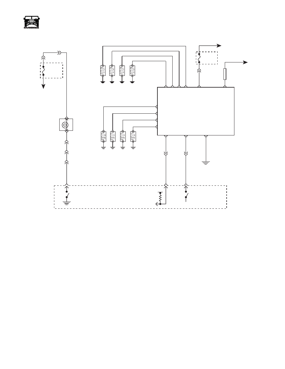
DTC P0380 Glow Plug Circuit Performance
Circuit Description
The glow plug system is used to assist in providing the heat re-
quired to begin combustion during engine starting at cold am-
bient temperatures. The glow plugs are heated before and
during cranking, as well as initial engine operation. The PCM
controls the glow plug “ON” times by monitoring coolant tem-
peratures and glow plug voltage. The PCM also monitors glow
plugs individually to detect a failure. Once a failure has been
detected, a diagnostic signal is sent to the PCM so the diagnos-
tic code and MIL can be activated. This is a type B code.
Action Taken When the DTC Sets
Hard start or no start and possible white smoke.
Conditions for Clearing the MIL/DTC
• The PCM will turn the MIL off after three consecutive
trips without a fault condition.
• A History DTC will clear when forty consecutive
warm-up cycles that the diagnostic does not fail (coolant
temperature has risen 5°C (40°F) from start up coolant
temperature and engine coolant temperature exceeds
71°C (160°F) that same ignition cycle).
• Use of a Scan Tool.
Diagnostic Aids
IF a P0380 DTC sets after the PCM has been flashed, the glow
plug system must be relearned. Refer to (LINK-GOTO-RE-
PAIR-609502) Glow Plug System Type Relearn. If glow plug
relay is stuck in the “ON” position, check for proper operation
of glow plugs. When glow plugs are commanded “ON” by the
Scan Tool, an internal PCM timer protects the glow plugs from
damage by cycling them “ON” for 3 seconds and then “OFF”
for 12 seconds. The glow plug relay battery feed wire nut
should be tested for proper torque. The California glow plug
system will send the following volages.
FUSE 3A
20 AMP
EXTERIOR
HOT IN RUN
AND START
GLOW PLUG
RELAY
IGN
POWER
FUSIBLE
LINK
WA
IT
WAIT TO START
LAMP CONTROL
C9-J
C9-A
C3-D1
C1-27
C28-C7
GLOW PLUGS RH
GLOW PLUG
RELAY
CONTROL
GLOWPLUG
FEEDBACK
SIGNAL
POWERTRAIN
CONTROL
MODULE
(PCM)
C27-D7
C27-C6
30 GY
466 YL
G1
#1
#3
#5
#7
BK
C5-A4
338 DB
C3-N7
RIGHT
BANK
OUTPUT
00-S12-011
B+
C5-C11
C5-B4
GLOW PLUGS LH
#2
#4
#6
#8
BATT +
LEFT
BANK
OUTPUT
RH STATUS
CENTER
5V
506 LB
239 PK
A
C
TO
STARTER
POS. STUD
B
B
C
D
A
D
C
B
A
D
FUSE 4B
5 AMP
INTERIOR
FUSE BOX
TO
IGNITION
SWITCH
86
PCM/Tech 1 Scan Tool
_____________________________________________________
®
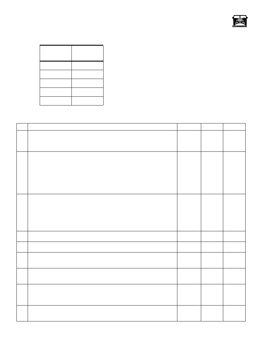
Test Description
Number(s) below refer to the number(s) on the diagnostic ta-
ble.
3-This step will determine if P0380 is a hard failure.
4-This step will determine if there is a short to voltage on the
signal circuit.
8-This step will determine if there is ignition voltage at the
glow plug relay.
10-This step will determine if the glow plug control circuit and
the PCM are working properly.
11-This step will determine if if there is a short to voltage an
the relay control circuit.
13-This step will determine if the glow plugs or the glow plug
harness is causing the P0380 DTC.
Signal
Voltage
Glow Plugs
5.0-5.6
None
2.3-2.8
1
1.3-1.8
2
0.8-1.4
3
Less than 1.1
4 or more
DTC P0380 - Glow Plug Circuit Performance
Step
Action
Value
Yes
No
1
Before clearing any DTC’s, use the scan tool Capture Info to save the Freeze Frame
and Failure Records for reference. The PCM’s data is deleted once the Clear Info
function is used.
Did you perform the On-Board Diagnostic (OBD) System Check?
Go to step
2.
2
If DTC P0380 set after a PCM reflash.
Connect a scan tool. Turn the ignition ON leaving the engine OFF. Observe the
Glow Plug System Type parameter on the scan tool.
Does the scan tool display the Glow Plug System Type as California?
Go to step
3.
Go to
(LINK-GO
TO-REPAI
R-609502)
Glow Plug
System
Type
Relearn
3
Connect a scan tool. Turn the ignition ON leaving the engeine OFF. Use the scan
tool to command the glow plugs ON and OFF. Observe the Glow Plug System Type
parameter on the scan tool.
Does the digital multimeter (DMM) display a voltage near the first specified value
with the glow plug comanded ON and near the second specified value with the glow
plug commanded OFF?
5.0-5.6
Volts
0.9-1.5
Volts
Go to step
7.
Go to step
4.
4
Does the scan tool display a glow plug voltage greater than the specified value?
5.6 Volts
Go to step
21.
Go to step
5.
5
Does the scan tool display a glow plug voltage greater than the specified value?
0.3 Volts
Go to step
10.
Go to step
6.
6
Turn the ignition ON leaving the engine OFF. Touch the battery feed stud on the
glow plug controller with an unpowered test lamp connected to ground.
Is the test light ON?
Go to step
8.
Go to step
25.
7
The DTC is intermittent. If any additional DTC’s were stored, refer to those
table(s).
Were ther any additional DTC’s stored?
Go to the
applicable
DTC table.
Go to
Diagnostic
Aids.
8
Disconnect the glow plug relay control connector. Turn the ignition ON with the
engine OFF. With an unpowered test lamp connected to ground, probe the glow plug
relay harness ignition feed circuit (CKT 239 PK).
Is the test light ON?
Go to step
9.
Go to step
16.
9
Turn the ignition ON with the engine OFF. Connect an unpowered test lamp to B+,
probe the glow plug relay ground circuit (BK).
Is the test light ON?
Go to step
10.
Go to step
17.

_____________________________________________________
PCM/Tech 1 Scan Tool 87
®
05745159
10
Turn the ignition ON with the engine OFF. Verify that the glow plug relay control
harness is disconnected. With a DMM connected to ground, probe the glow plug
relay control circuit (466 YL) at the glow plug relay harness connector. Use a scan
tool to command the glow plugs ON and OFF.
Does the DMM display a voltage near the first specified value with the glow plugs
commanded ON and near the the second specified voltage with glow plugs com-
manded OFF?
9-12 Volts
0 volts
Go to step
12.
Go to step
11.
11
Is the voltage equal to or more than the specified value all the time?
1.0 Volt
Go to step
23.
Go to step
18.
12
Turn the ignition ON leaving the engine OFF. Recconect the glow plug relay control
harness. With a DMM connected to ground, backprobe the glow plug relay signal
circuit (506 LB) at the PCM harness connector. Use a scan tool to command the
glow plugs ON. Observe the DMM while the glow plugs are commanded ON.
Is the voltage at the specified value?
5.0-5.6
Volts
Go to step
21.
Go to step
13.
13
Turn the ignition OFF. Disconnect the right and left bank glow plug output circuit
connectors at the glow plug relay. With an unpowered test lamp connected to B+,
probe each circuit.
Does each circuit turn ON the test lamp?
Go to step
26.
Go to step
14.
14
Turn the ignition OFF. Disconnect each glow plug connector at the glow plug that
did not illuminate the test lamp. With an unpowered test lamp connected to B+,
probe the terminal on the glow plug.
Does each glow plug illuminate the test lamp?
Go to step
26.
Go to step
25.
15
Turn the ignition OFF. Disconnect each glow plug connector at the glow plug. With
an unpowered test lamp connected to B+, probe each circuit at the glow plug output
connectors.
Is the test lamp OFF at each of the circuits?
Go to step
20.
Go to step
27.
16
Repair an open or a short to ground in the glow plug relay ignition feed circuit
(CKT 239 PK).
Did you complete the repair?
Go to step
30.
17
Repair any opens or poor connections in the glow plug relay ground circuit (BK).
Did you complete the repair?
Go to step
30.
18
Inspect the glow plug relay control circuit (466 YL) for an open or short to ground.
If the glow plug relay control circuit is open or shorted to ground, repair as neces-
sary.
Did you find and correct the condition?
Go to step
30.
Go to step
19.
19
Inspect the glow plug relay control circuit (CKT 466 YL) for a proper connection at
the PCM and replace the terminal if necessary.
Did you find an improper connection and make the necessary repair?
Go to step
30.
Go to step
29.
20
Inspect the glow plug relay signal circuit (CKT 506 LB) for an open or short to
ground. If the glow plug relay signal circuit is open or shorted to ground, repair as
necessary.
Did you find and correct the condition?
Go to step
30.
Go to step
28.
21
Inspect the glow plug relay signal circuit (CKT 506 LB) for a proper connection at
the PCM and replace the terminal if necessary.
Did you find an improper connection and make the necessary repair?
Go to
step30.
Go to step
22.
22
Test for a short to voltage in the glow plug relay signal circuit (CKT 506 LB).
Did you find the improper condition?
Go to step
30.
Go to step
28.
23
Test for a short to voltage in the glow plug relay control circuit (CKT 466 YL) .
Did you find and correct the condition?
Go to step
30.
Go to step
29.
24
Repair the open or poor connection on the battery feed circuit.
Did you complete the repair?
Go to step
30.
25
Replace any glow plug that did not illuminate the test lamp.
Did you complete the repair?
Go to step
30.
DTC P0380 - Glow Plug Circuit Performance
Step
Action
Value
Yes
No

88
PCM/Tech 1 Scan Tool
_____________________________________________________
®
26
Repair the open or poor connections in the glow plug harness.
Did you complete the repair?
Go to step
30.
27
Repair the short to ground in the glow plug harness.
Did you complete the repair?
Go to step
30.
28
Replace the glow plug relay.
Did you complete the repair?
Go to step
30.
29
THE NEW PCM MUST BE PROGRAMMED.Replace the PCM.
Did you complete the repair?
Go to step
30.
30
Use a scan tool to clear the DTC’s. Start the engine. Allow the engine to idle until
the engine reaches normal operating temperature. Select the DTC and the specific
DTC function. Enter the DTC number which was set. Operate the vehicle, with the
Conditions for Setting this DTC, until the scan tool indicates the diagnostic Ran.
Does the scan tool indicate the diagnostic Passed?
Go to step
31.
Go to step
2.
31
Does the scan tool display any addition undiagnosed DTC’s?
Go to the
applicable
DTC table.
System
OK.
DTC P0380 - Glow Plug Circuit Performance
Step
Action
Value
Yes
No
Нет комментариевНе стесняйтесь поделиться с нами вашим ценным мнением.
Текст