Hummer H1 (2002+). Manual — part 227

_____________________________________________________
Electrical System 12-133
®
05745159
Figure 12-130: Compass Mirror Schematic
COMP
ASS
IGNITION
FUSE
2C
10 AMP
FUSE
3C
7.5 AMP
COMPASS
MIRROR
GROUND
TEMP
SENSOR
407 PK
400 LG
140 OR
59 BK
767 BR
B
F
G
A
D
C1-61
C2-8
G4
G2
TO HEATED
WINDSHIELD
SWITCH
G4
59 BK
400 LG
TO
IGNITION
SWITCH
TO
IGNITION
SWITCH
580 BR
TEMP
SENSOR
00-S12-003.1
COMPASS
CUTOUT
RELAY
INTERIOR
FUSE
BOX
C13
BACK-UP
LIGHT
SWITCH
298 BR
58 BK
C2-26
REVERSE
INHIBIT
IGNITION
C2-27
C1-43
GROUND
768 BK
E
4
1
3
2
6
7
4-1-00
12-134
Electrical System
______________________________________________________
®
POWER SIDE MIRROR
Description
The side mirrors have an option of an internal heater element
to aid in defrosting. Heated side mirrors will only be available
if the truck is equipped with a heated windshield.
The power side mirror system components are: two side mir-
rors with internal vertical and horizontal control motors (and
optional heater elements), the power mirror switch, and the
heated windshield switch (optional).
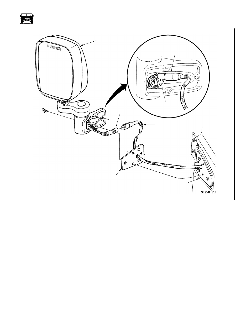
Power Side Mirror Replacement
Removal
1.
Remove the three mounting screws securing the power
mirror assembly and gasket to mounting plate (Figure 12-
130.2).
2.
Disconnect the power mirror assembly connector from the
door jumper harness.
3.
Inspect the gasket and replace if damaged.
Installation
NOTE:
Ensure the door jumper harness is routed through the
gasket before connecting the harness to the power mirror as-
sembly.
1.
Connect the power mirror assembly connector to the door
jumper harness (Figure 12-130.2).
NOTE:
Wires from the power mirror assembly must be coiled
in the mirror housing to ensure clearance to the attachment
points.
2.
Align the power side mirror and the gasket with the
mounting plate on the door.
3.
Install the three mounting screws
.
3-1-01
___________________________________________________
Electrical System 12-134.1
®
05745159
Figure 12-130.2 Power Mirror Assembly Removal
POWER MIRROR
ASSEMBLY
MOUNTING
SCREW
CONNECTOR
GASKET
MOUNTING
PLATE
DOOR
JUMPER
HARNESS
DOOR
JUMPER
HARNESS
CONNECTOR
3-1-01

12-134.2
Electrical System
____________________________________________________
®
Power Side Mirrors Inoperative
Step
Action
Value(s)
Yes
No
1
Are both mirrors INOP?
Go to step 2.
Go to step 4.
2
Remove the power mirror switch. With a DVOM check
circuit 517 (PK) for battery voltage. Is the specified
voltage present?
> 12.6v
Go to step 3.
Repair circuit 517
(PK) between the
power mirror switch
and fuse 3H in the
interior fuse box.
3
With a DVOM check the resistance to ground on cir-
cuit 59 (BK). Does the resistance meet the specifica-
tions?
< 0.2
Ω
Replace the power
mirror control
switch.
Repair circuit 59
(BK) between the
power mirror switch
and ground G4.
4
Is only the left side power mirror INOP?
Go to step 5.
Go to step 7
5
Remove the left side power mirror. With a DVOM
back probe circuits 942 (OR) with the positive lead,
and circuit 59 (BK) with the negative lead. With the
DVOM set to check voltage move the power mirror
switch to the left side and then up. In both cases the
voltage should change from 0v to 12v. Does the volt-
age change?
0v - off
12v - left
0v - off
12v - up
Replace the power
side mirror.
Go to step 6.
6
With a DVOM check resistance on circuit 942 (OR)
between the power side mirror and the power mirror
control switch. Does the resistance on the circuit meet
specifications?
< 0.2
Ω
Replace the power
mirror switch.
Repair circuit 942
(OR) between the
power side mirror
and the power win-
dow switch.
7
Remove the left side power mirror. With a DVOM
back probe circuits 944 (OR) with the positive lead,
and circuit 59 (BK) with the negative lead. With the
DVOM set to check voltage move the power mirror
switch to the left side and then up. In both cases the
voltage should change from 0v to 12v. Does the volt-
age change?
0v - off
12v - left
0v - off
12v - up
Replace the power
side mirror.
Go to step 8.
8
With a DVOM check resistance on circuit 944 (OR)
between the power side mirror and the power mirror
control switch. Does the resistance on the circuit meet
specifications?
< 0.2
Ω
Replace the power
mirror switch.
Repair circuit 944
(OR) between the
power side mirror
and the power win-
dow switch.
3-1-01
Нет комментариевНе стесняйтесь поделиться с нами вашим ценным мнением.
Текст