Hummer H1 (2002+). Manual — part 226
_____________________________________________________
Electrical System 12-129
®
05745159
AUTO-DIMMING REAR VIEW MIRROR WITH
ELECTRONIC COMPASS AND TEMPERATURE
(OPTION)
Description
The Auto-Dimming rear view mirror has the capability to
change the opacity of the mirror glass to prevent glare. When a
following vehicles head lamps hit the rear light detection sen-
sor, the mirror’s opacity will lessen. The now translucent mir-
ror will allow light to pass through it. This effectively lessens
the glare on the driver, much like moving the angle on a man-
ual mirror.
Removal
1.
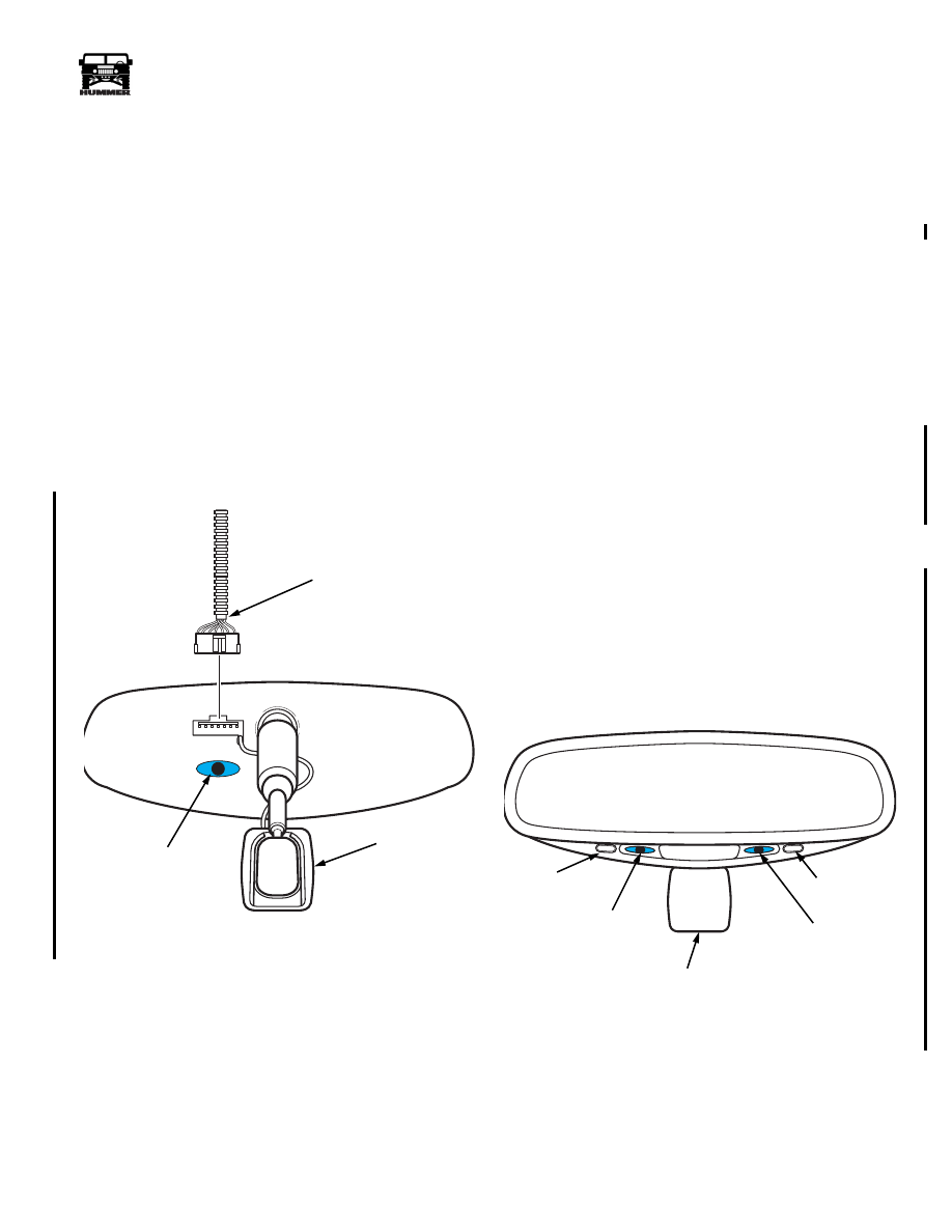
Disconnect mirror jumper harness from the rear of the
mirror assembly (See Figure 2-126).
2.
Gently push upward on the mirror head and the compass
pod together until the mirror assembly is free of the
windshield button.
Figure 2-126: Auto-Dimming Mirror Jumper
Harness Connection
Installation
1.
Grasp the mirror head with both hands
2.
Slide the mirror down onto the window mount and gently
rock side to side until mirror base is seated. Do not force
the mirror onto the mount.
3.
Connect the mirror jumper harness to the rear of the newly
installed mirror.
4.
Set calibration and zone adjustments. (Refer to Auto-
Dimming compass mirror calibration and zone
adjustment).
AUTO-DIMMING COMPASS MIRROR CALI-
BRATION AND ZONE ADJUSTMENTS
Calibration Adjustment
1.
Start the engine.
2.
Press and hold the auto-dimming power button until
“CAL” appears in the display and release (Figure 2-127).
3.
Drive
slowly
in a circle away from large metal buildings
and power lines until the “CAL” disappears.
Zone Adjustment
1.
Press and hold the mode button until “ZONE” appears in
the display (See Figure 2-127).
2.
Each depression of the mode button will change the zone
number in sequence. Refer to the zone chart below for the
zone number of your area of operation (Figure 2-128).
3.
When the desired zone is reached, allow the mirror to go
to normal mode then turn off the ignition.
Figure 2-127: Auto-Dimming Rear View Mirror
9-OM2-035.2
MIRROR JUMPER
HARNESS
AMBIENT
LIGHT SENSOR
COMPASS
POD
9-OM2-033.2
COMPASS
POD
AUTO-DIMMING
POWER BUTTON
AUTO-DIMMING
POWER L.E.D
REAR LIGHT
DETECTION
SENSOR
MODE
BUTTON
4-1-00

12-130
Electrical System
______________________________________________________
®
Figure 2-128: Magnetic Zone Chart
4-1-00
_____________________________________________________
Electrical System 12-131
®
05745159
AMBIENT TEMPERATURE SENSOR
Removal
1.
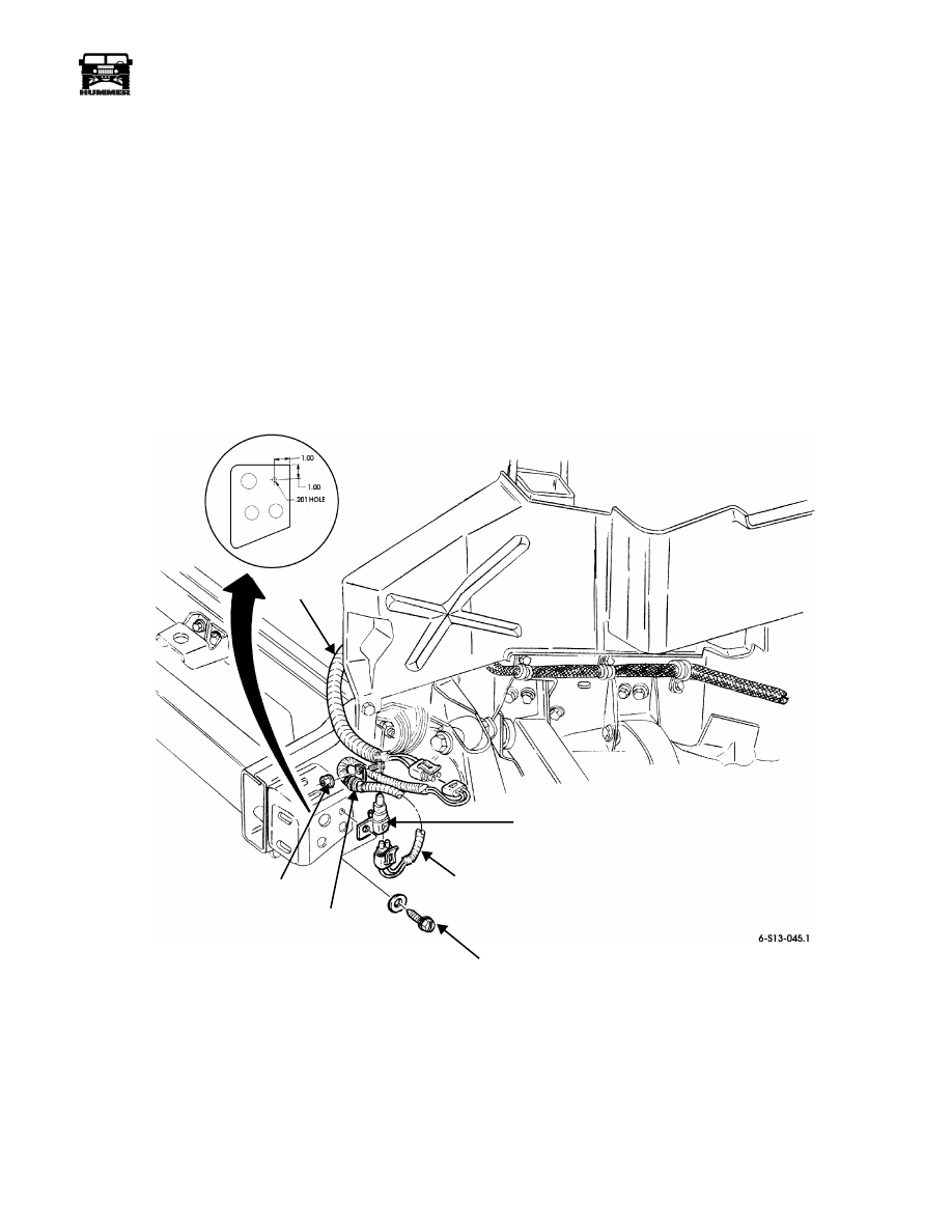
Remove existing nut, cushioned clamp, and ambient tem-
perature sensor jumper harness from the body harness
(Figure 12-129).
2.
Disconnect the ambient temperature sensor jumper
harness from the sensor.
3.
Remove self-tapping screw and ambient temperature
sensor from the frame.
Installation
1.
Install ambient temperature sensor to the frame with self-
tapping screw (Figure 12-129).
2.
Connect the ambient temperature sensor harness to the
sensor.
3.
Connect the ambient temperature sensor harness to the
body harness.
4.
Using cushioned clamp, secure jumper harness to body
harness mounting clamp with existing nut and bolt.
Figure12-129: Ambient Temperature Sensor
AMBIENT
BODY
JUMPER
TEMPERATURE
SENSOR
HARNESS
HARNESS
EXISTING
NUT
SELF-TAPPING
SCREW
CUSHIONED
CLAMP
4-1-00
Section 12 Electrical System

12-132
Electrical System
______________________________________________________
®
Compass Mirror Display Inoperative
Step
Action
Value(s)
Yes
No
1
Turn the ignition to the ON position, and heated
windshields OFF.
Is compass mirror display operating?
No problem
found, or inter-
mittent.
Go to step 2.
2
Gain access to C13, with the ignition ON measure
voltage at pin B. Is voltage present?
Approximate
battery voltage
Go to step 4.
Go to step 3.
3
Check for open, or short to ground in CKT 407
between compass cutout relay and compass mir-
ror, and CKT 400 between compass cutout relay
and fuse 2C in the interior fuse box.
Are any problems found?
Repair open or
short to ground
in CKT 407 and
CKT 400.
Replace mirror
cutout relay.
4
Check continuity to ground at C13 pin A, is resis-
tance to ground below specified?
>.2
Ω
Replace com-
pass mirror
Go to step 5.
5
Check for open or bad connection in CKT 59
between compass mirror and G4.
Are any problems found?
Repair open or
bad connection
in CKT 59.
No problem
found, go to
step 1.
Compass Mirror Temperature Display Showing OC, SC or Wrong Temp
Step
Action
Value(s)
Yes
No
1
Does compass mirror display show “OC” or “SC”
in place of the temperature?
Go to step 3.
Go to step 2.
2
Gain access to C13, measure resistance between pin
D and ground. With the vehicle at room temperature
(70°F), does resistance measured match specifica-
tions?
Approx.12 K
Ω
Replace
com-
pass mirror.
Go to step 3.
3
Measuring resistance to ground at C13 Pin D,
does meter display open?
OL
Go to step 4.
Repair bad con-
nection at C13.
4
Disconnect temperature sensor from underbody
harness. Measure resistance between the two pins
of the sensor. With the vehicle at room tempera-
ture (70°F), is resistance in range specified?
Higher temperature gives lower resistance read-
ings.
Approx.12 K
Ω
Go to step 5.
Replace the
temperature
sensor.
5
Measure resistance to ground at temperature sen-
sor connector pin A. Is resistance below speci-
fied?
<.2
Ω
Go to step 6.
Repair open or
bad connection
in CKT 58
between tem-
perature sensor
and G2.
6
Check for open, bad connection, or short to
ground in CKT 767 between temperature sensor
and compass mirror. Are any problems found?
Repair open,
bad connection,
or short to
ground in CKT
767.
Replace the
compass mirror.
4-1-00
Нет комментариевНе стесняйтесь поделиться с нами вашим ценным мнением.
Текст