Hummer H1 (2002+). Manual — part 285

_____________________________________________________
PCM/Tech 1 Scan Tool 73
®
05745159
DTC P0238 - Turbocharger (TC) Boost Sensor Circuit High Voltage
Step
Action
Value(s)
Yes
No
1
Important:
Before clearing DTC(s) use the scan tool “Capture Info” to
record freeze frame and failure records for reference, as data will be lost
when “Clear Info” function is used.
Was the
“On-Board Diagnostic (OBD) System Check”
performed?
—
Go to Step 2.
Go to
OBD
System Check.
2
1. Scan tool connected.
2. Engine idling.
Does the scan tool display a Boost Pressure greater than or equal to the
specified value?
202 kPa
(4.8v)
Go to Step 3. Go to Step 4.
3
1. Turn the ignition “OFF”.
2. Disconnect the Boost sensor electrical connector.
3. Turn the ignition “ON”.
Does the scan tool display a Boost Pressure less than or equal to the speci-
fied value?
9 kPa
Go to Step 5.
Go to Step 9.
4
DTC is intermittent. If no additional DTCs are stored, refer to “Diagnostic
Aids”. If additional DTCs are stored, refer to those chart(s).
Are additional DTCs stored?
—
Go to the
Applicable
DTC table.
Go to
Diagnostic
Aids.
5
1. Ignition ON, engine OFF>
2. With a J–39200 connected to ground, probe the 5 volt reference circuit at
the boost sensor harness.
Is voltage greater than the specified value?
5.2v
Go to Step 10. Go to Step 6.
6
1. Boost sensor disconnected.
2. Jumper the Boost sensor ground circuit at the harness with a test light
connected to B+.
Is the test light “ON”.
—
Go to Step 7.
Go to Step 11.
7
Check the Boost sensor for a restriction.
Was a problem found.
—
Go to Step 13.
Go to Step 8.
8
Replace the faulty Boost sensor.
Is the action complete?
—
Go to Step 13.
—
9
Check for a short to voltage in the Boost sensor signal circuit.
Was a problem found?
—
Go to Step 13. Go to Step 12.
10
Check for a short to ground in the Boost sensor circuit.
Was a problem found?
—
Go to Step 13. Go to Step 12.
11
Repair the Boost sensor circuit as necessary.
Is the action complete?
—
Go to Step 13.
—
12
Replace the faulty PCM.
Notice:
If the PCM is faulty, the new PCM must
be programmed. Go to
PCM replacement and programming procedures.
Is the action complete?
—
Go to Step 13.
—
13
1. Using the Scan Tool, select “DTC”, “Clear Info”.
2. Start engine and idle at normal operating temperature.
3. Select “DTC”, “Specific”, then enter the DTC number which was set.
4. Operate vehicle within the conditions for setting this DTC as specified in
the supporting text.
Does the Scan Tool indicate that this diagnostic Ran and Passed?
—
Go to Step 14.
Go to Step 2.
14
Using the Scan Tool, select “Capture Info”, “Review Info”.
Are any DTCs displayed that have not been diagnosed?
—
Go to the
applicable
DTC table
System OK.
74
PCM/Tech 1 Scan Tool
_____________________________________________________
®
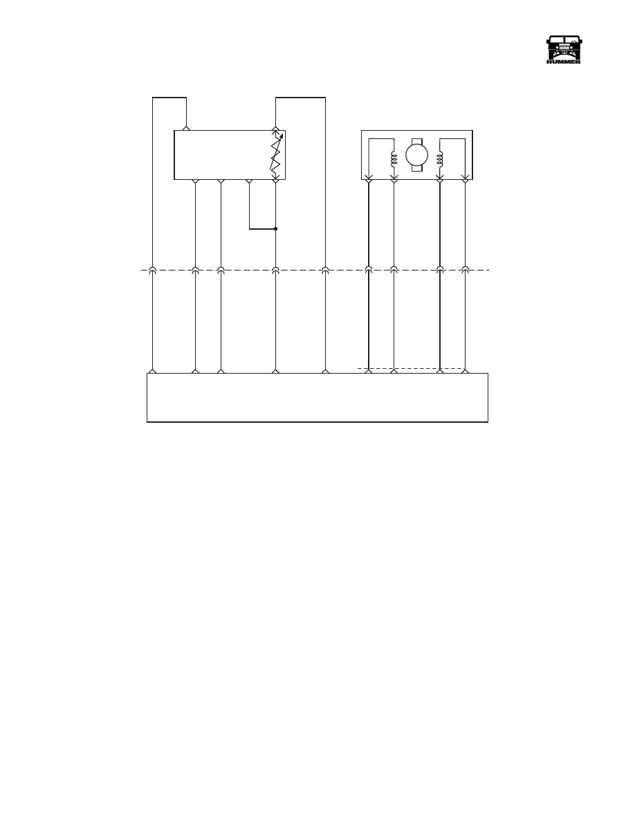
DTC P0251 Injection Pump Cam System
Circuit Description
The optical sensor provides a pump cam signal to the PCM by
counting pulses on the sensor disk located in the injection
pump. The pump cam is one of the most important inputs by
the PCM for fuel control and timing. This test monitors the
number of crankshaft position pulses that have occurred since
the last cam pulse. The physical one to one correspondence be-
tween the pump cam and the crankshaft implies if more crank
pulses are detected than cam pulses, cam pulses have been
missed. This is a type A DTC.
Conditions for Setting the DTC
• RPM less than 300.
• 8 consecutive cam pulses missing for 8 #1 cylinder.
or
• RPM greater than or equal to 300.
• 8 consecutive cam pulses missing for 32 #1 cylinder.
Action Taken When the DTC Sets
Backup fuel.
Conditions for Clearing the MIL/DTC
• The PCM will turn the MIL off after three consecutive
trips without a fault condition.
• A History DTC will clear when forty consecutive
warm-up cycles that the diagnostic does not fail (coolant
temperature has risen 5°C (40°F) from start up coolant
temperature and engine coolant temperature exceeds
71°C (160°F) that same ignition cycle).
• Use of a Scan Tool (ignition must be cycled before DTC
is cleared).
Diagnostic Aids
When PCM is in backup fuel, fast idle and poor performance
problems will exist. If P0251 is also stored, there is a possible
problem with signal circuit. P0251 and P0370 will set if vehi-
cle has run out of fuel.
Test Description
Number(s) refer to the number(s) on the diagnostic table.
2. This step will determine if this is a hard or intermittent DTC.
4. This step will determine if there is a 5 volt reference.
6. This step will check to see if the sensor is sending a signal
back to the PCM.
A
E
B
F
D
C
5 VOLT
REFERENCE
OPTICAL/ FUEL
TEMP SENSOR
PUMP CAM
SENSOR
SIGNAL
HIGH
RESOLUTION
SIGNAL
SENSOR
GROUND
M
D
A
B
C
C5
C3
B8
C1
C12
C2
375 GY
442 BR
703 OR
156 PK
225 YL
C27-D14
C29-A4
C29-A2
C27-D9
C27-C8
FUEL TEMP
SIGNAL
SENSOR
GROUND
HIGH
RES
SIGNAL
CAM
SENSOR
SIGNAL
5 VOLT
REFERENCE
INJECTION TIMING
STEPPEN MOTOR (ITS)
A3
A2
A6
A7
709 RD
708 TN
710 OR
71
1 YL
C29
A8
A9
A10
A7
ITS
HI
ITS
LO
ITS
LO
ITS
HI
POWERTRAIN
CONTROL
MODULE
9-S12-070

_____________________________________________________
PCM/Tech 1 Scan Tool 75
®
05745159
DTC P0251 - Injection Pump Cam System
Step
Action
Value(s)
Yes
No
1
Important:
Before clearing DTC(s) use the scan tool “Capture Info”.
Was the
“On-Board Diagnostic (OBD) System Check”
performed?
—
Go to Step 2.
Go to
OBD
System Check.
2
Start and idle engine. With the throttle closed, observe the Cam Ref Missed
display on scan tool. Does scan tool display specified value?
8
Go to Step 4. Go to Step 3.
3
DTC is intermittent.
Are additional DTCs stored?
—
Go to DTC
table.
Go to
Diagnostic
Aids.
4
1. Ignition “OFF”.
2. Disconnect the Optical/Fuel temperature sensor electrical connector.
3. Ignition “ON” engine “OFF”.
4. Measure voltage between Optical/Sensor 5 volt circuit and chassis ground
at harness connector. Is voltage at specified value?
5v
Go to Step 5.
Go to Step 7.
5
Probe the sensor ground circuit with a test light connected to B+ at the har-
ness connector. Is test light “ON”?
—
Go to Step 6.
Go to Step 8.
6
1. Reconnect the Optical/Fuel temperature sensor.
2. Start and idle engine.
3. With scan tool, command 900 rpm.
4. On Hertz (Hz) scale, back probe Cam signal circuit at PCM.
Is Hertz reading at specified value?
60 Hz
(± 3 Hz)
Go to Step 12. Go to Step 11.
7
1. Remove electrical harness filter from vehicle.
2. Check resistance on 5 volt reference circuit (terminal “A”).
Is resistance greater than specified value?
2.0 Ohms
Go to Step 15.
Go to Step 8.
8
1. Ignition “OFF”.
2. Electrical harness filter removed from vehicle.
3. Disconnect the PCM and check the Optical/Sensor 5 volt circuit for an
open, short to ground, or short to the sensor ground circuit.
4. If Optical/Sensor 5 volt circuit is open or shorted to ground, repair it as
necessary.
Was 5 volt circuit open or shorted to ground?
—
Go to Step 16. Go to Step 10.
9
1. Check for open or poor sensor ground terminal connection at PCM.
2. If a problem is found, repair as necessary.
Was a repair performed?
—
Go to Step 16. Go to Step 14.
10
Check the Optical/Fuel Temperature 5 volt reference circuit for a poor con-
nection at the PCM and replace terminal if necessary.
Did the terminal require replacement?
—
Go to Step 16. Go to Step 14.
11
1. Ignition “OFF”.
2. Check the Cam signal circuit for an open or short to ground.
3. If Cam signal circuit is open or shorted to ground, repair it.
Was the Cam signal circuit open or shorted to ground?
—
Go to Step 16. Go to Step 13.
12
Check for a poor connection at the PCM harness terminal and replace.
Did the terminal require replacement?
—
Go to Step 16. Go to Step 14.
13
Replace injection pump.
Is action complete?
—
Go to Step 16.
—
14
Replace the faulty PCM.
Notice:
If the PCM is faulty, the new PCM must be
programmed. Is the action complete?
—
Go to Step 16.
—
15
Replace electrical harness filter.
Is action complete?
—
Go to Step 16.
—

76
PCM/Tech 1 Scan Tool
_____________________________________________________
®
16
1. Using the Scan Tool, select “DTC”, “Clear Info”.
2. Start engine and idle at normal operating temperature.
3. Select “DTC”, “Specific”, then enter the DTC number which was set.
4. Operate vehicle within the conditions for setting this DTC.
Does the Scan Tool indicate that this diagnostic Ran and Passed?
—
Go to Step 17.
Go to Step 2.
17
Using the Scan Tool, select “Capture Info”, “Review Info”.
Are any DTCs displayed that have not been diagnosed?
—
Go to DTC
table
System OK.
DTC P0251 - Injection Pump Cam System
Step
Action
Value(s)
Yes
No
Нет комментариевНе стесняйтесь поделиться с нами вашим ценным мнением.
Текст