Hummer H1 (2002+). Manual — part 163
_____________________________________________________________________
Body 10-23
®
05745159
Installation
1.
Secure bracket to B-pillar and body with washers and bolts
(Figure 10-31). Tighten bolts to 12 lb-ft (16 N•m).
2.
Secure retractor mounting bracket to B-pillar with washers
and bolts. Tighten bolts to 24 lb-ft (33 N•m).
3.
Route seat belt assembly through opening in lower B-
pillar trim and secure retractor to retractor mounting
bracket with washer and bolt. Tighten bolts to 35-40 lb-ft
(47-55 N•m).
4.
Secure lower B-pillar trim to B-pillar with screw/washer
assemblies.
NOTE:
Steps 5 and 6 are applicable to all vehicles except two-
door vehicles with the enlarged cab.
5.
Connect body harness connector to courtesy light lamp
assembly.
6.
Secure courtesy light lamp assembly and mounting
bracket to lower B-pillar trim on B-pillar with washers and
rivets.
7.
Secure anchor bracket to bracket with washer and screw/
washer assembly. Tighten screw/washer assembly to 35-
40 lb-ft (47-55 N•m).
8.
Secure D-ring and webbing guide cover to B-pillar with
washer and screw/washer assembly.
9.
Route seat buckle electrical connector through grommet in
inner kick panel and plug seat buckle electrical connector
into roof harness connector (Figure 10-30).
10. Install inner kick panel.
11. Secure seat buckle to body with screw/washer assembly
and washer. Tighten screw/washer assembly to 35-40 lb-ft
(47-55 N•m).
12. Install seat.
DRIVER’S AND FRONT PASSENGER’S SEATS
Standard Driver’s and Passenger’s Seat
Pedestal Repair
NOTE:
Seat pedestal repair is similar for driver’s and front
passenger’s seats. This procedure covers the driver’s seat ped-
estal.
Removal
1.
Remove driver’s seat pedestal.
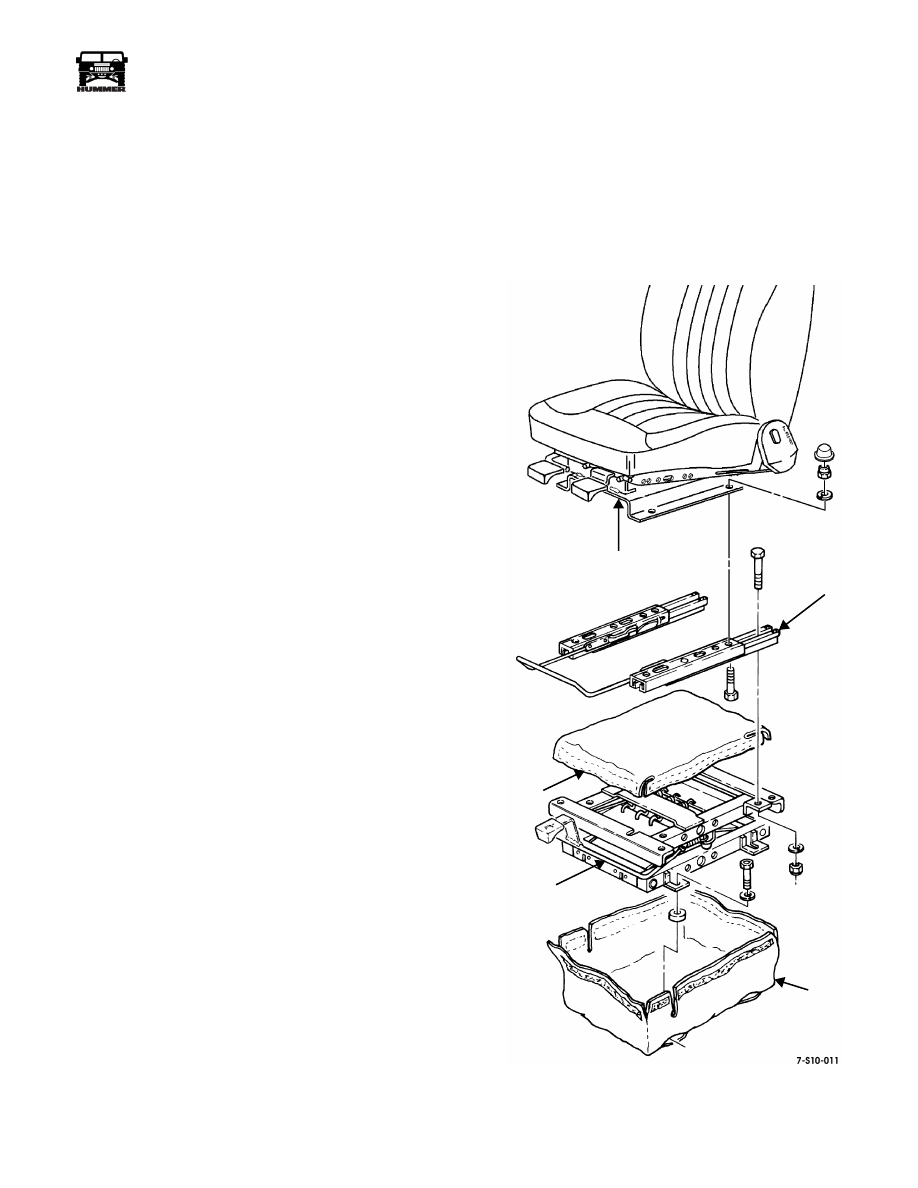
2.
Remove bag from height adjuster (Figure 10-32).
3.
Remove nuts, lockwashers, and bolts securing height
adjuster to slide set and remove height adjuster and cover.
4.
Remove nuts, lockwashers, and bolts securing riser to
slide set and remove riser.
Installation
1.
Secure riser to slide set with bolts, lockwashers, and nuts
(Figure 10-32). Tighten nuts to 24 lb-ft (33 N•m).
2.
Secure cover and height adjuster to slide set with bolts,
lockwashers, and nuts.
3.
Install bag on height adjuster.
4.
Install driver’s seat pedestal.
Figure 10-32: Seat Pedestal Assembly Breakdown
RISER
SLIDE SET
BAG
HEIGHT ADJUSTER
COVER
10-24
Body
______________________________________________________________________
®
Reclining Driver’s and Front Passenger’s
Seat Replacement
NOTE:
Reclining driver’s and front passenger’s seats are re-
placed similarly. This procedure covers the passenger’s seat.
Removal
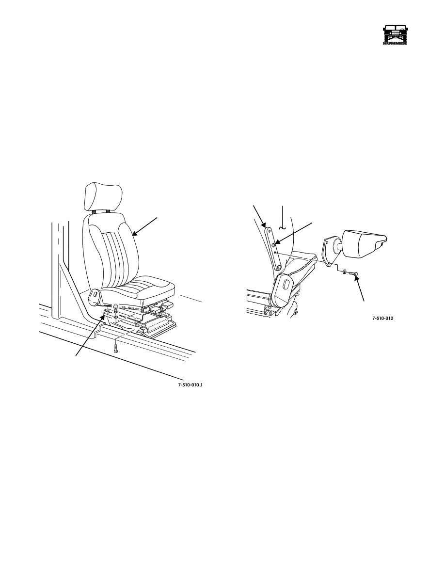
Remove bolts, washers, and passenger’s seat from seat base
(Figure 10-33).
Installation
Secure passenger’s seat to seat base with washers and bolts.
Tighten bolts to 15 lb-ft (20 N•m) (Figure 10-33).
Figure 10-33: Reclining Front Seat Replacement
Driver’s and Front Passenger’s Seat Pedestal
Assembly Replacement
NOTE:
Seat pedestal assembly replacement for driver’s and
front passenger’s seats is similar. This procedure covers the
driver’s seat pedestal.
Removal
1.
Remove seat from seat pedestal.
2.
Remove four bolts, lockwashers, and washers securing
seat pedestal to floor.
3.
Remove seat pedestal and four spacers from vehicle.
Installation
1.
Install four spacers and seat pedestal in vehicle.
2.
Secure seat pedestal to floor with four washers,
lockwashers, and bolts. Tighten bolts to 24 lb-ft (33 N•m).
3.
Secure seat to seat pedestal.
Driver’s Seat Armrest Replacement
Removal
1.
Remove plastic caps covering exposed screws.
2.
Remove short screws and lockwashers attaching armrest
to bracket (Figure 10-34).
3.
If bracket needs to be replaced, remove long screws
attaching bracket to seat support.
Figure 10-34: Driver’s Seat Armrest Mounting
Installation
NOTE:
If bracket was removed, perform steps 1 through 3.
1.
Secure bracket to seat support with one of the long screws.
Do not tighten screw (Figure 10-34).
2.
Use large center hole in bracket to locate upper bracket
mounting hole in seat support.
3.
Secure top section of bracket to seat support with the other
long screw. Tighten both long screws to 120 lb-in. (14
N•m).
4.
Secure the armrest to the bracket with the short screws and
lockwashers. Tighten the short screws to 120 lb-in. (14
N•m).
5.
Position the plastic caps over the exposed screw heads.
NOTE:
The entire armrest can be positioned vertically or hori-
zontally by pushing the armrest up or down. To adjust the an-
gle of the armrest while it is in the horizontal position, use the
adjusting knob located under the front end of the armrest.
6.
Use the adjusting knob to position the armrest as
necessary.
PASSENGER’S SEAT
SEAT BASE
SEAT SUPPORT
BRACKET
SHORT SCREW
LONG SCREW
ARMREST
_____________________________________________________________________
Body 10-25
®
05745159
REMOVABLE LOAD BARRIER AND MOUNTING
BRACKETS REPLACEMENT (STATION WAGON)
Removal
1.
Remove drive screws and carpet assembly from front and
back of removable load barrier (Figure 10-35).
2.
Remove necessary interior trim to gain access to mounting
brackets.
3.
Remove removable load barrier by lifting barrier up and
out of mounting brackets on inner wheel house panels.
4.
Remove rivets and mounting bracket from left inner wheel
house panel.
5.
Remove rivets and mounting bracket from right inner
wheel house panel.
Inspection
Inspect bumper strips. If damaged, replace.
Installation
1.
Secure mounting bracket to left inner wheel house panel
with rivets (Figure 10-35).
2.
Secure mounting bracket to right inner wheel house panel
with rivets.
3.
Install removable load barrier in mounting brackets.
4.
Install interior trim.
5.
Secure carpet assembly to front and back of removable
load barrier with drive screws.
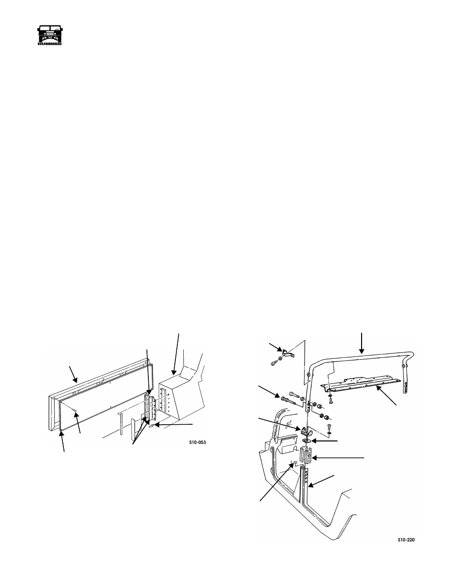
Figure 10-35: Removable Load Barrier
Location
INTERIOR TRIM
B-Bar Replacement
NOTE:
This procedure covers replacement of the B-bar for all
vehicles except open top models and 2-door models without an
enlarged cab.
Removal
1.
Remove seat belt assemblies.
2.
Remove trim from B-bar.
3.
Remove domelight.
NOTE:
It may be necessary to remove any duct tape or tie
straps securing electrical wiring harnesses to B-bar.
4.
Remove screws, washers, and headliner support from B-
bar (Figure 10-36).
5.
Remove screws, lockwashers, and mounting brackets from
mounting blocks.
6.
Remove B-pillar seals and rabbet seals from B-pillar.
Inspect and discard seals if damaged.
7.
Remove locknuts, washers, and strikers from B-pillar.
8.
Remove six locknuts, washers, bolts and mounting blocks
from B-pillar.
9.
Remove B-bar.
10. Remove screws, washers, and two trim mounting brackets
from B-bar.
Figure 10-36: B-Bar Mounting
REMOVABLE
MOUNTING
BUMPER STRIPS
RIVET
SCREW
CARPET ASSEMBLY
BRACKET
LOAD BARRIER
RIGHT INNER WHEEL
HOUSE PANEL
DRIVE
B-BAR
HEADLINER
B-PILLAR
MOUNTING
B-PILLAR
RABBET
MOUNTING
STRIKER
TRIM
MOUNTING
BRACKET
SUPPORT
SEAL
BLOCK
SEAL
BRACKET
10-26
Body
______________________________________________________________________
®
Installation
1.
Secure trim mounting brackets to B-bar with four washers
and screws (Figure 10-36).
2.
Install B-bar.
3.
Secure mounting blocks to B-pillar with washers, bolts
and locknuts. Tighten locknuts to 24 lb-ft (33 N•m).
4.
Secure strikers to B-pillar with washers and locknuts.
5.
Install B-pillar seals and rabbet seals on B-pillar.
6.
Secure mounting brackets to mounting blocks with
lockwashers and screws.
7.
Secure headliner support to B-bar with washers and
screws.
8.
Install domelight.
9.
Install trim on B-bar.
10. Install seat belt assemblies.
Passenger’s Compartment Trim
Replacement
Removal
1.
Remove rear seats.
2.
Remove overhead speakers (Section 12).
3.
Remove seat belt assemblies.
4.
Remove screw/washer assemblies and B-bar center trim
from roof (Figure 10-37).
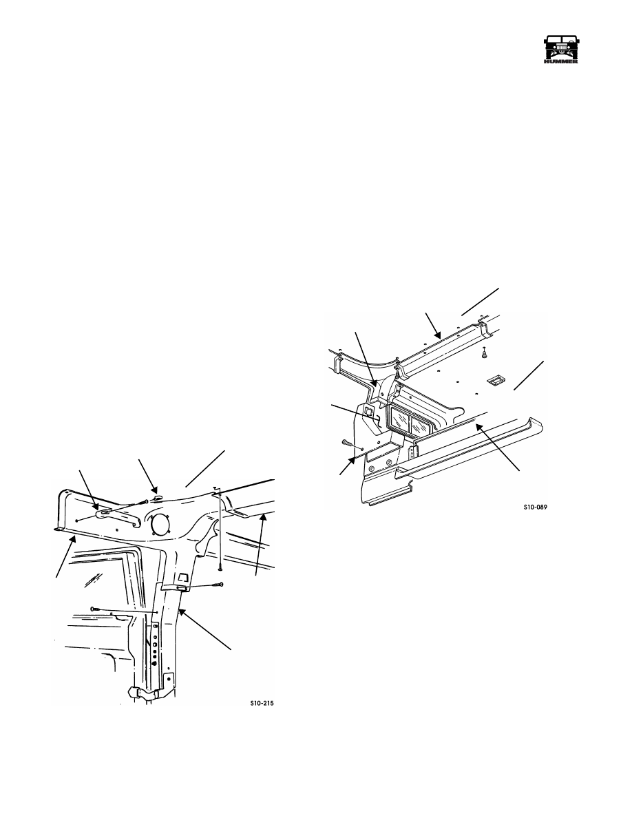
Figure 10-37: Driver Side Interior Trim Component
Identification
5.
Remove covers, screws, and grab handle from trim.
6.
Remove screw/washer assemblies and upper B- bar trim
from roof.
7.
Remove screws, washers, and lower B-pillar trim from B-
pillar.
NOTE:
Perform steps 8 through 10 for station wagon models
only.
8.
Remove screw/washer assemblies and C-pillar center trim
from roof (Figure 10-38).
9.
Remove screw/washer assemblies and upper C-pillar trim
from roof.
10. Remove screw/washer assemblies and lower C-pillar trim
from lower C-pillar.
Figure 10-38: Station Wagon Interior Trim
Component Identification
11. Remove screw/washer assemblies and trim panel from
rear compartment wall (Figure 10-39)
GRAB
COVER
ROOF
UPPER
B-BAR
TRIM
HANDLE
CENTER
B-BAR
TRIM
B-PILLAR
TRIM
~
CENTER TRIM
HEADLINER
REAR
LOWER
COMPARTMENT
WALL
C-PILLAR
UPPER
C-PILLAR
C-PILLAR
TRIM
TRIM
C-PILLAR
~
ROOF
~
Нет комментариевНе стесняйтесь поделиться с нами вашим ценным мнением.
Текст