Hummer H1 (2002+). Manual — part 115
____________________________________________________________
Brake System 7-19
®
05745159
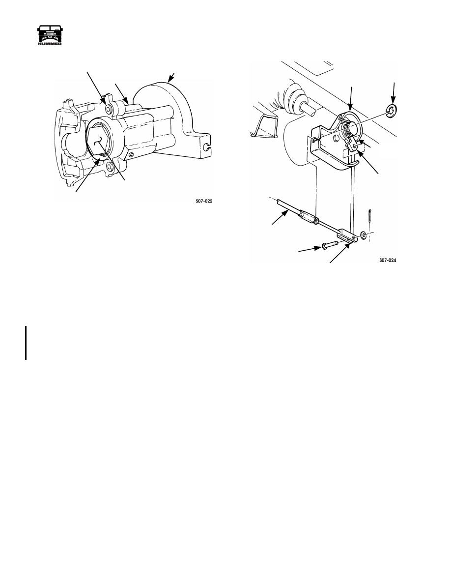
Figure 7-20: Rear Dual Brake Caliper
Installation
WARNING: Ensure brake pads are installed with lin-
ings facing rotor. Failure to do this will cause poor per-
formance and damage to equipment and may result in
injury.
1.
Check brake pad backing plate notches for burrs or excess
coating and ensure that the pad will fit the adapter slide
with enough clearance to afford stick-free movement.
CAUTION:
Remove any excess lubricant that may have
squeezed out from between mating surfaces. Do not allow any
lubricant to come in contact with brake pad friction material
or brake rotor surfaces.
2.
Lubricate caliper guide pins, sleeves and adapter slides
with Permatex
®
Ultra Disc Brake Caliper Lube prior to
installation.
NOTE:
Always apply thread-locking compound to the tapped
holes.
3.
Apply thread-locking compound to tapped holes of
adapter.
4.
Using special tool J–42553, rotate caliper piston in a
clockwise direction, and at the same time apply force on
outer piston face until caliper piston is seated in piston
bore (Figure 7-20).
5.
Position caliper and yoke on adapter and rotor. Secure
yoke to adapter with two washers and capscrews. Using a
crowsfoot, tighten capscrews to 40 lb-ft (54 N•m)
(Figure 7-19).
6.
Install parking brake cable to caliper cable bracket and
secure with clip (Figure 7-21).
Figure 7-21: Rear Dual Brake Caliper Cable
CAUTION:
Ensure lever is in contact with caliper cable
bracket stop. Damage to equipment and poor performance will
result if not aligned properly. Ensure that clevis and clevis pin
are aligned to the lever. Do not move lever to accommodate a
maladjusted clevis. Damage to equipment and poor perfor-
mance will result.
7.
Install parking brake clevis to lever with clevis pin,
washer, and cotter pin. Check position of lever and ensure
it is in contact with caliper cable bracket stop.
8.
Adjust rear dual service/parking brake.
CALIPER CABLE BRACKET
CALIPER
DUST BOOT
CALIPER PISTON FACE
BUSHING
CLIP
PARKING BRAKE
CABLE
CLEVIS PIN
PARKING BRAKE
LEVER
CLEVIS
CALIPER
CABLE BRACKET
CALIPER CABLE
BRACKET STOP
3-1-01
7-20
Brake System
_____________________________________________________________
®
REAR DUAL SERVICE/PARKING BRAKE
CALIPER REPLACEMENT
Removal
1.
Put transmission in PARK, chock wheels, and release
parking brake.
2.
Remove cotter pin, washer, and clevis pin securing
parking brake clevis to lever. Discard cotter pin
(Figure 7-21).
3.
Remove clip and parking brake cable from caliper cable
bracket. Discard clip.
4.
Disconnect brake line from coupling (Figure 7-22).
5.
Remove coupling and copper washer from caliper.
Figure 7-22: Rear Dual Brake Components
CAUTION: Caliper must be supported during removal to pre-
vent damage to brake line.
6.
Remove two capscrews, washers, yoke, and caliper from
adapter.
7.
Slide yoke and caliper guide pins out from caliper.
Cleaning and Inspection
NOTE:
Clean all components, examine for wear or damage,
and replace if necessary. Apply a light coat of brake compo-
nent lubricant on adapter slides.
1.
Clean mating surfaces of caliper and adapter and lubricate
adapter slides with brake component lubricant
(Figures 7-17 and 7-19).
2.
Inspect caliper and caliper piston face for pitting or
damage (Figure 7-24).
3.
Inspect caliper cable bracket for looseness, damage, and
rotation
4.
Inspect piston dust boot and bushing for tears or
deterioration.
5.
Clean cooling fins of rotor (Figure 7-22).
6.
Inspect rotor for heat checks, discoloration, pitting, or
damage.
7.
Inspect yoke and caliper guide pins for corrosion. Perform
step 8 if corroded, if not, perform step 9.
8.
Remove caliper guide pins from yoke. Discard caliper
guide pins.
9.
Inspect brake pads for glazing, oil saturation, or wear. If
glazed, oil saturated, or if brake lining thickness is less
than 1/8 in. (3.2 mm), replace both pads and pads on
opposite caliper.
CAUTION: Ensure that grease and oil are not in contact with
rotor and/or brake pad friction surfaces. Failure to do so will
result in damage to equipment and poor performance.
ADAPTER
ROTOR
YOKE
CALIPER
CALIPER
COUPLING
BUSHING
PLASTIC
GUIDE PIN
MOUNTING
SLIDE
SURFACES
SLEEVE
BRAKE
LINE/HOSE
COPPER
WASHER
____________________________________________________________
Brake System 7-21
®
05745159
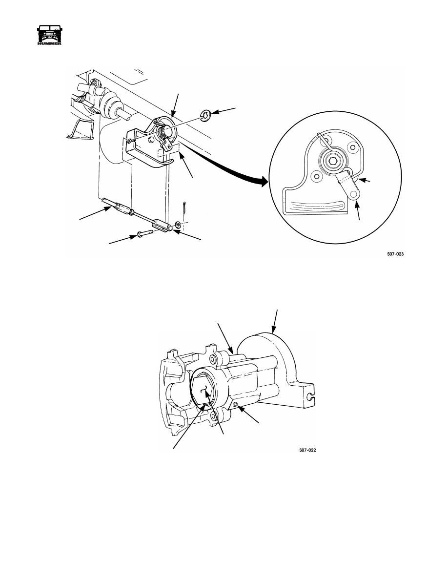
Figure 7-23: Rear Dual Service/Parking Brake Caliper Cable Bracket
Figure 7-24: Rear Caliper and Bleeder Valve
CALIPER CABLE
CLIP
LEVER
PARKING
CLEVIS
PIN
BRAKE CLEVIS
PARKING
BRAKE CABLE
CALIPER
CABLE
BRACKET
STOP
LEVER
BRACKET
CALIPER PISTON FACE
DUST BOOT
CALIPER CABLE BRACKET
CALIPER
BLEEDER VALVE

7-22
Brake System
_____________________________________________________________
®
Installation
1.
Open bleeder valve and depress piston into caliper while
rotating piston in a clockwise direction, and at the same
time apply pressure until piston is seated in piston bore
(Figure 7-24).
NOTE:
Perform step 2 only if caliper guide pins were re-
placed.
2.
Apply thread-locking compound to threads of caliper
guide pins and install caliper guide pins in yoke. Tighten
caliper guide pins to 30 lb-ft (41 N•m) (Figure 7-25).
3.
Lubricate caliper guide pins, sleeves and adapter slides
with Permatex
®
Ultra Disc Brake Caliper Lube prior to
installation. Slide yoke and caliper guide pins into caliper
4.
Apply thread-locking compound to tapped holes of
adapters.
5.
Position caliper and yoke on adapter and rotor. Install
caliper and yoke on adapter with two washers and
capscrews. Using crowfoot, tighten capscrews to 40 lb-ft
(54 N•m).
6.
Install copper washer and coupling on caliper and connect
brake line to coupling.
7.
Install parking brake cable on caliper cable bracket and
secure with clip (Figure 7-23).
CAUTION:
Ensure lever is in contact with caliper cable
bracket stop. Damage to equipment and poor performance will
result if not aligned properly. Ensure that clevis and clevis pin
are aligned to lever. Do not move lever to accommodate a mis-
adjusted clevis, or damage to equipment and poor perfor-
mance will result.
8.
Install parking brake clevis on lever and secure with clevis
pin, washer, and cotter pin.
9.
Check position of lever and ensure it is in contact with
caliper cable bracket stop.
10. Bleed brake system.
11. Adjust rear dual service/parking brake.
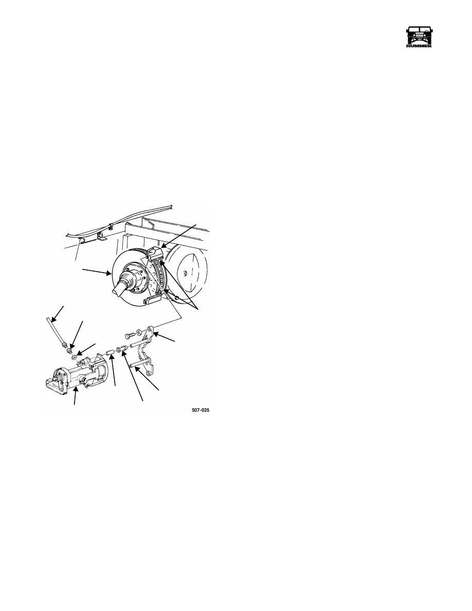
Figure 7-25: Rear Brake Components
TAPPED HOLE
ADAPTER
YOKE
CALIPER
CALIPER
ROTOR
SLEEVE
BUSHING
GUIDE PIN
COUPLING
BRAKE
LINE/HOSE
COPPER
WASHER
4-1-00
Нет комментариевНе стесняйтесь поделиться с нами вашим ценным мнением.
Текст