Hummer H1 (2002+). Manual — part 224
_____________________________________________________
Electrical System 12-121
®
05745159
POWER DOOR LOCK REAR DOOR AND
JUMPER HARNESS REPLACEMENT
Removal
NOTE:
Left and right rear power door locks harness replace-
ment procedures are identical.
1.
Remove front seat.
2.
Remove trim from B-beam and B-pillar (Section 10).
3.
Remove side trim and outer kick panel (Section 10).
4.
Remove rear door trim (Section 10).
NOTE:
Vapor barrier may be positioned under velcro strip If
so, cut around velcro strip to remove vapor barrier.
5.
Remove vapor barrier and moisture barrier flap.
6.
Remove capscrew and clamp securing rear door harness to
door reinforcement.
7.
Disconnect rear door harness from jumper harness.
8.
Remove convoluted tubing from rear door harness.
9.
Remove two-lead connector from rear door harness with
pin extraction tool.
10. Remove capscrew, washer, nut and lockwasher assembly,
and P-clamp from rear door harness and B-pillar.
11. Pull harness through rubber grommet in B-pillar.
12. Remove and inspect grommet. Discard if damaged.
13. Remove two capscrews and support bracket from rear
door.
14. Pull harness through door bushing and remove support
bracket from harness. Inspect support bracket bushing.
Replace if damaged.
15. Inspect bushing in rear door. Replace if damaged.
16. Disconnect door harness connector from actuator lead.
17. Disconnect clip from door reinforcement and remove from
rear door harness.
18. Remove rear harness from door.
19. Disconnect jumper harness from dash harness at A-pillar.
Remove tie straps and jumper harness (Figure 2-116).
Figure 2-116: Door Harness Connection
POWER WINDOWS AND LOCKS
JUMPER HARNESS
A-PILLAR
CROSS BODY HARNESS
4-1-00
Section 12 Electrical System

12-122
Electrical System
______________________________________________________
®
Installation
NOTE:
Lubricate bushings, rubber grommet, and door harness
teflon cover with silicone spray.Install clip and support bracket
on rear door harness (Figure 2-117).
1.
Install harness in door bushing.
2.
Install support bracket in rear door with two capscrews.
3.
Install rubber grommet in B-pillar.
4.
Install harness through grommet until yellow tape touches
the back of B-pillar.
5.
Install P-clamp on harness at yellow tape and B-pillar with
capscrew, washer and lockwasher and nut assembly.
6.
Install two-lead connector on rear door harness, matching
wire colors to jumper harness. Connect harness to jumper
harness.
7.
Route rear door harness along bottom of rear door. Secure
harness to door reinforcement with clip.
8.
Attach door harness connector to actuator. Tighten power
window motor mounting screws, if loose.
9.
Install convoluted tubing on rear door harness wires and
secure with black electrical tape.
10. Install P-clamp on rear door harness at yellow tape area
and secure to door reinforcement with one capscrew.
11. Install vapor barrier and moisture barrier flap.
12. Install rear door trim (Section 10).
13. Install side trim and outer kick panel (Section 10).
14. Install trim on B-pillar and B-beam (Section 10).
15. Install front seat (Section 10).
Figure 2-117: Door Harness Routing
DOOR
REINFORCEMENT
B-PILLAR
REAR DOOR
HARNESS
TIE WRAP
JUMPER HARNESS
TIE STRAP
ACTUATOR
POWER LEAD
DOOR HARNESS
TEFLON COVER
SUPPORT
BRACKET BUSHING
P-CLAMP
P-CLAMP
DOOR BUSHING
TWO LEAD
CONNECTOR
PLASTIC TUBING
B-PILLAR
RUBBER GROMMET
SUPPORT
BRACKET
CLIP
4-1-00
_____________________________________________________
Electrical System 12-123
®
05745159
POWER WINDOW AND DOOR LOCKS FRONT
DOOR HARNESS REPLACEMENT
Removal
1.
Remove front outer kick panels (Section 10).
2.
Remove power window and door lock switches from door.
3.
Remove front door trim, vapor barrier, and moisture
barrier flap from door (Section 10).
NOTE:
Tag leads for installation.
4.
Disconnect 4-way and 6-way harness connectors from
power windows and door locks body harness connectors
(Figure 2-118).
NOTE:
Perform step 6 for vehicles equipped with power mir-
rors.
5.
Disconnect two harness connectors from power mirrors
body harness connectors.
6.
Remove screw, nut and lockwasher assembly, and clamp
securing harness to A-pillar. Discard nut and lockwasher
assembly
7.
Remove harness wires from 4-way and 6-way connectors.
NOTE:
Lubricate bushings, grommet, and harness teflon
cover with silicone spray.
8.
Pull harness through A-pillar rubber grommet.
9.
Remove and inspect A-pillar rubber grommet. Replace if
damaged.
NOTE:
Perform step 11 for vehicles equipped with power mir-
rors.
10. Disconnect two harness connectors from power mirrors
door jumper harness connectors (Figure 2-120).
11. Remove self-tapping screw and clamp securing harness to
door reinforcement (Figure 2-120).
12. Remove two self-tapping screws and harness mounting
bracket from door assembly.
13. Pull harness through door bushing.
14. Inspect door bushing and replace if damaged.
15. Remove harness mounting bracket and mounting bracket
bushing from harness. Inspect bushing and replace
if damaged.
16. Disconnect harness connector from power window
regulator (push locking tab up on bottom of connector).
17. Disconnect harness connector from power door locks
actuator.
18. Remove retainer and harness from door assembly.
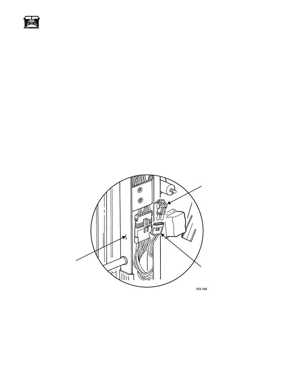
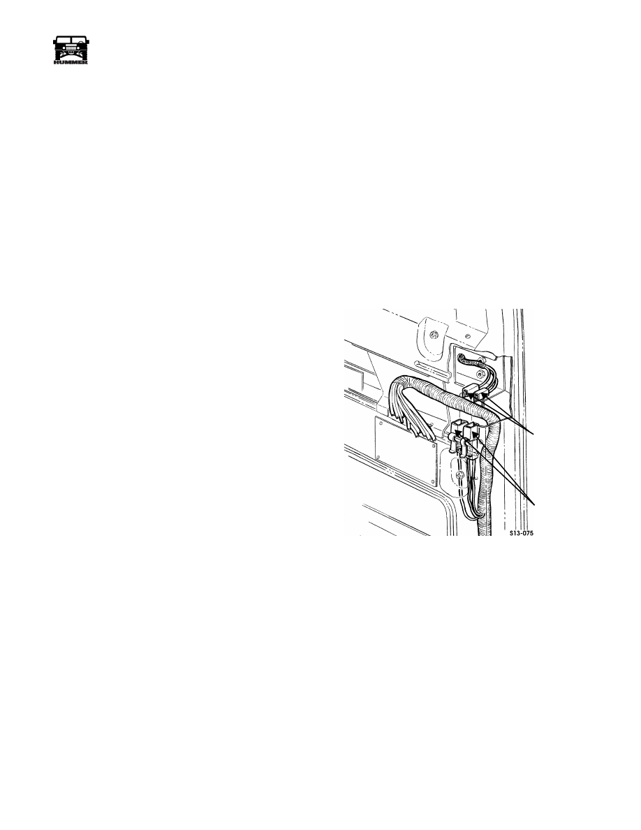
Figure 2-118: Power Mirrors Door Jumper Harness
POWER MIRRORS
DOOR JUMPER
CONNECTORS
HARNESS
CONNECTORS
HARNESS
4-1-00
12-124
Electrical System
______________________________________________________
®
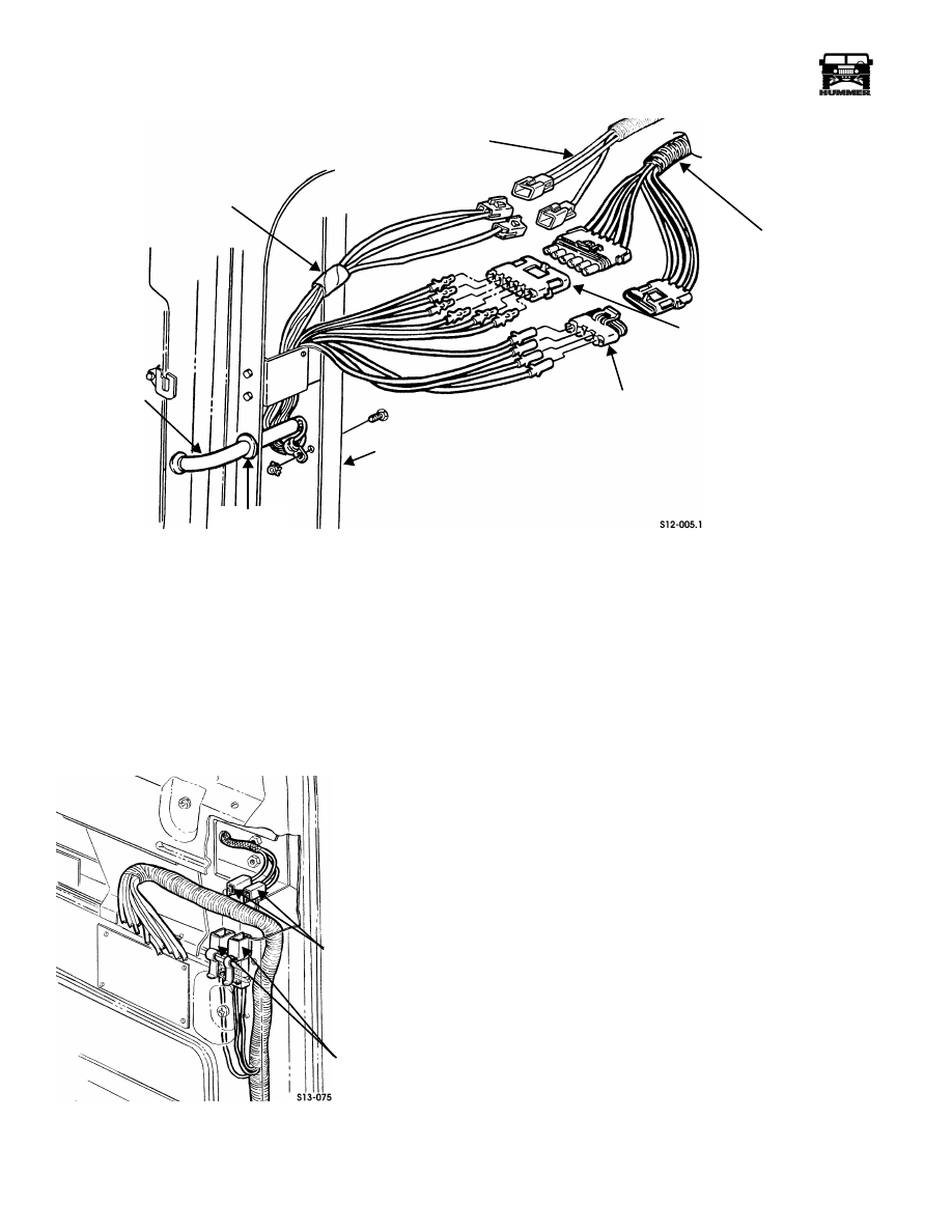
Figure 2-119: Power Windows and Door Locks Connections
Installation
NOTE:
Lubricate bushing, grommet, and harness teflon cover
with silicone spray.
1.
Route harness through harness mounting bracket, mount-
ing bracket bushing, and door bushing (Figure 2-120).
2.
Install harness mounting bracket on door assembly with
two self-tapping screws (Figure 2-121).
3.
Route harness through A-pillar rubber grommet
(Figure 2-119).
Figure 2-120: Power Mirrors Door Jumper Harness
NOTE:
When connecting harness wires to 4-way and 6-way
connectors, ensure wire colors align with mating connector wires.
4.
Connect harness wires to 4-way and 6-way connectors.
5.
Connect 4-way and 6-way harness connectors to power
windows and door locks body harness connectors.
NOTE:
Perform step 6 for vehicles equipped with power mirrors.
6.
Connect two harness connectors to power mirrors body
harness connectors.
7.
Secure harness to A-pillar with clamp, self-tapping screw,
and nut and lockwasher assembly.
NOTE:
Perform step 8 for vehicles equipped with power mirrors.
NOTE:
Be careful to match the wire colors, since the harness
connectors can be interchanged.
8.
Connect two harness connectors to power mirrors door
jumper harness connectors (Figure 2-119).
9.
Connect harness connector to power window regulator
(Figure 2-121).
10. Connect harness connector to power door lock actuator.
11. Secure harness to door reinforcement with clamp and self-
tapping screw.
12. Secure harness to door assembly with retainer.
13. Install moisture barrier flap, vapor barrier, and door trim
panel on door (Section 10).
14. Install power window and door lock switches on door.
15. Install front outer kick panels (Section 10).
16. Connect battery ground cable (Section 12).
17. Check power windows and door locks for proper operation.
FRONT DOOR
POWER WINDOWS
AND DOOR LOCKS
BODY HARNESS
6-WAY
4-WAY
A-PILLAR
TEFLON TUBE
CONNECTOR
CONNECTOR
HARNESS
POWER MIRRORS
BODY HARNESS
GROMMET
POWER MIRRORS
DOOR JUMPER
CONNECTORS
HARNESS
CONNECTORS
HARNESS
4-1-00
Нет комментариевНе стесняйтесь поделиться с нами вашим ценным мнением.
Текст