Hummer H1 (2002+). Manual — part 214
______________________________________________________
Electrical System 12-81
®
05745159
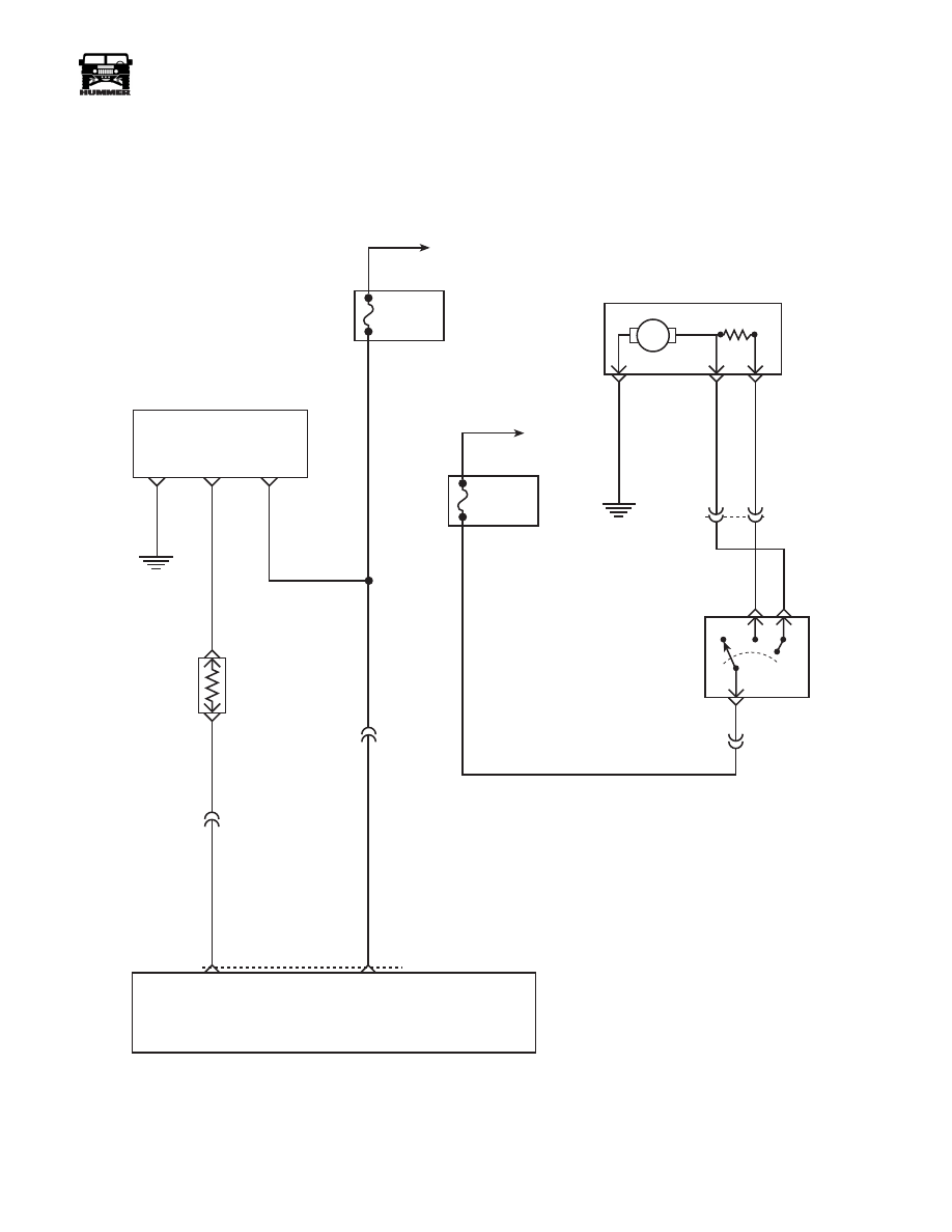
Figure 12-95: HVAC Temp Blend Door/Rear Blower
F
E
8 PIN
FUSE 7C
30A
INTERIOR
HOT IN RUN
AND START
FUSE 6C
20A
INTERIOR
HOT IN RUN
AND START
M
REAR
HVAC
BLOWER
H
L
G4
405 OR
404 YL
E4
E3
C6
346 PK
C6-C3
399 DG
C6-G1
TEMPERATURE
DOOR MOTOR
58 BK
GROUND
POSITION
SIGNAL
IGN
INPUT
G4
7
8
10
C6-J1
RESISTOR
MODULE
(62K
Ω
)
402 LB
HVAC
CONTROL
HEAD
TEMP BLEND
MOTOR CONTROL
IGN INPUT
+
REAR HVAC
BLOWER
SWITCH
9 - S 1 2 - 0 6 3
59 BK
4-1-00
12-82
Electrical System
_______________________________________________________
®
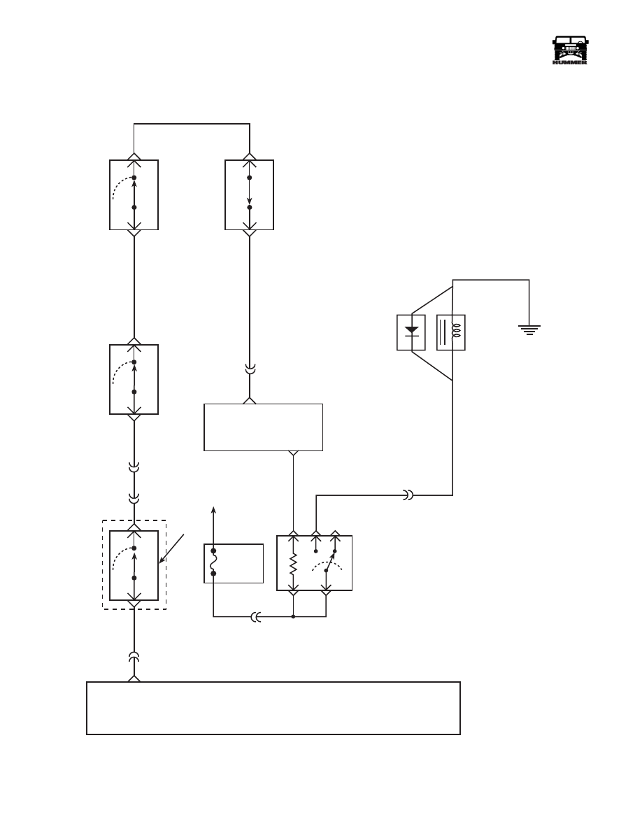
Figure 12-96: HVAC Compressor Schematic
COMPRESSOR
RELAY
86
87
85
30
FUSE 2C
10A
INTERIOR
HOT IN RUN
AND START
POWERTRAIN
CONTROL
MODULE
(PCM)
A/C
REQUEST
A/C
COMPRESSOR
ENABLE
DIODE
COMPRESSOR
CLUTCH
G1
HIGH
PRESSURE
CUTOUT
SWITCH
LOW
PRESSURE
SWITCH
438 OR
C1-39
C4-2
347 YL
HVAC
U N I T
TEMP
CUTOUT
SWITCH
C6-J8
8 PIN
H
A/C
REQUEST
439 YL
C4-5
C27-C2
C28-D5
198 TN
440 DB
C1-1
400 LG
C4-8
348 BR
HVAC
CONTROL
HEAD
AMBIENT
TEMPERATURE
SWITCH
9-S12-061
4-1-00

______________________________________________________
Electrical System 12-83
®
05745159
Windshield Wiper Motor Inoperative All Speeds
Step
Action
Value(s)
Yes
No
1
Gain access to the wiper motor connector under
the windshield trim. Using a DVOM set to mea-
sure resistance, check resistance to ground on the
brown wire (CKT 59). Is the resistance below the
specified value?
<.2
Ω
Go to step 2.
Repair open or
bad connection
in CKT 59
between the
wiper motor and
G4.
2
Turn the ignition switch to the “RUN” position
and the wiper switch to “LOW”. Using a DVOM
set to measure voltage, check for voltage at the
dark green wire (CKT 63). Is the specified voltage
present?
12v
Replace the
wiper motor.
Go to step 3.
3
Remove the wiper switch from the instrument
panel and turn the ignition to the “RUN” position.
Using a DVOM set to measure voltage, back
probe the yellow wire (CKT 65) at the wiper
switch. Is the specified voltage present?
12v
Replace wiper
switch.
Repair the open
or bad connec-
tion in CKT 65
between the
wiper switch
and fuse 7G.
Windshield Wiper Motor Inoperative on LOW
Step
Action
Value(s)
Yes
No
1
Remove the wiper switch from the instrument
panel. Turn the ignition to the “RUN” position
and the wiper switch to “LOW”. Using a DVOM
set to measure voltage, back probe the green wire
(CKT 63). Is the specified voltage present?
12v
Go to step 3.
Go to step 2.
2
Using a DVOM set to measure voltage, back
probe the yellow wire (CKT 65) at the wiper
switch. Place the ground lead on a known good
ground. With the ignition on, is the specified volt-
age present?
12v
Replace the
wiper switch.
Repair open or
bad connection
in CKT 65
between the
wiper switch
and fuse 7G.
3
Gain access to the wiper motor connector behind
the windshield trim. Using a DVOM set to mea-
sure voltage, backprobe the dark green wire (CKT
63). Turn the ignition switch to the “RUN” posi-
tion, and set the wiper switch to “LOW”. Is the
specified voltage present?
12v
Replace the
wiper motor.
Repair the open
or bad connec-
tion in CKT 63
between the
wiper motor and
the wiper
switch.
4-1-00

12-84
Electrical System
_______________________________________________________
®
Windshield Wiper Motor Inoperative on High
Step
Action
Value(s)
Yes No
1
Remove the wiper switch from the instrument
panel. Turn the ignition to the “RUN” position
and the wiper switch to “HIGH”. Using a DVOM
set to measure voltage, back probe the red wire
(CKT 61). Is the specified voltage present?
12v
Go to step 3.
Go to step 2.
2
With the ignition switch in the RUN” position,
check the voltage at the yellow wire (CKT 65). Is
the specified voltage present?
12v
Replace the
wiper switch.
Repair the open
or bad connec-
tion on CKT 65
between the
wiper switch
and fuse 7G.
3
Gain access to the wiper motor connector under
the windshield trim. Turn the ignition switch to
the “RUN” position and the wiper switch to the
“HIGH” position. Using a DVOM check the volt-
age at the red wire (CKT 61). Is the specified volt-
age present?
12v
Replace the
wiper motor.
Repair the open
or bad connec-
tion on CKT 61
Between the
wiper motor and
the wiper
switch.
Windshield Wipers Intermittent Speeds Inoperative
Step
Action
Value(s)
Yes
No
1
Do the windshield wipers work normally on the
low and high speeds?
Go to step 2.
Refer to the
diagnostic chart
for the specific
problem on the
standard wiper
diagnosis.
2
Remove the wiper switch from the instrument
panel. Disconnect the wiper switch from the har-
ness.Using a DVOM measure resistance between
terminals 2 and 3. Is the resistance below the
specified value?
<.2
Ω
Connect the
intermittent
wiper switch to
the harness.
Go to step 3.
Replace the
wiper switch.
3
Turn the ignition switch to the “RUN” position
and the intermittent wiper switch to “MEDIUM
DELAY” . Using a DVOM set to measure volt-
age, back probe the brown wire (CKT 945) at the
intermittent switch. Voltage should pulse from 12
volts to 0 volts every 2-7 seconds depending on
position of switch. Is the voltage in the specified
range.
12v pulse
2-7 seconds
Go to step 5.
Go to step 4.
4-1-00
Нет комментариевНе стесняйтесь поделиться с нами вашим ценным мнением.
Текст