Hummer H1 (2002+). Manual — part 87
___________________________________________
Transmission/Transfer Case 5-147
®
05745159
Installation
1.
Work shifter boot cover lip into tunnel opening and align
edges carefully to match opening.
2.
Set shift control assembly into tunnel. Verify that fastener
holes are positioned properly and shifter boot cover lip is
not exposed.
3.
Secure shift control assembly to tunnel.
4.
Install bezel on shift control assembly.
5.
Attach shift control rods to shift control assembly.
6.
Fasten velcro and snaps to close shifter boot cover
opening.
7.
Properly position heat shield and tighten mounting clamps
securely.
SHIFT CONTROL ASSEMBLY INSTALLATION
1.
If cover plate and seal were removed, install new seal and
plate. Then install wire harness and shift knobs.
2.
Lubricate housing shift mechanism with spray lube.
3.
Work interlock cable through boot and connect cable to
shift housing (Figure 5-56).
4.
Connect harness wires to switches and bulb.
5.
Secure switch wires with new tie straps and slide boot up
against housing. Be sure wire connectors to body harness
are pulled through boot and secured with tie strap.
6.
Install shift indicators and bulb if removed.
7.
Seat shift control assembly in tunnel opening and secure
with assembly attaching bolts. Tighten bolts to 6 lb-ft (8
N•m) torque.
8.
Install two shift control housing boot protectors.
9.
Connect transmission and transfer case shift rods to shift
arms in control housing (Figure 5-54).
10. Install inner kick panel.
TRANSMISSION SHIFT ROD REPLACEMENT
1.
Place shift lever in neutral.
2.
Remove cotter pin, washer, and trunnion from housing
shift arm.
3.
Remove cotter pin and washer from shift rod rear
trunnion. Disconnect trunnion and remove wave washer
and shift rod from shift rod lever (Figure 5-62).
NOTE:
Mark positions of trunnions on shift rods for installa-
tion reference.
4.
Remove cotter pins securing trunnions to levers and
remove rod.
5.
Remove bolts attaching shift rod lever and bracket and
remove lever and bracket.
6.
Install new lever and bracket.
7.
Install lever rod and shift rod. Adjust rods and linkage as
described in Transmission Shift Linkage Adjustment
Procedure.
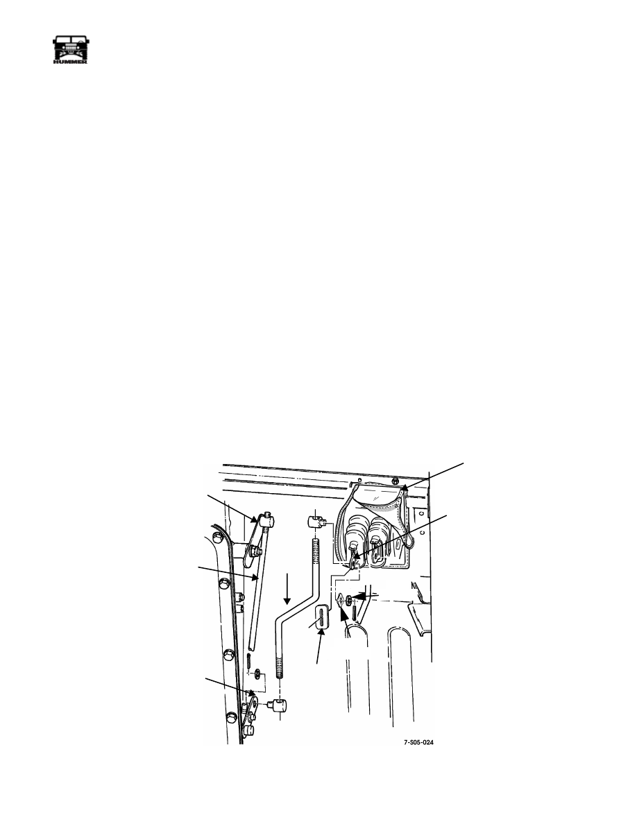
Figure 5-62: Shift Linkage Disassembly/Assembly
SHIFT ARM
SHIFT
SHIFT ROD
LEVER AND
BRACKET
LEVER ROD
TRANSMISSION
SHIFT LEVER
SHIFT CONTROL
HOUSING
ROD
BOOT
PROTECTOR
WAVY
WASHER
FLAT
WASHER
5-148
Transmission/Transfer Case
___________________________________________
®
SHIFT LINKAGE ADJUSTMENT
1.
Move shift lever to manual low (1) range.
2.
Disconnect transmission shift rod from arm in shift control
housing.
3.
Verify that transmission shift lever (Figure 5-63) is in
manual low (1) range. If not, disconnect lever trunnion
and adjust trunnion in, or out as needed. Then reconnect
lever rod to shift lever.
4.
Connect shift rod to shift control arm and check indicator
alignment at shift lever. If indicator is not quite aligned,
turn shift rod trunnion in or out to align.
5.
Verify that shift rod and lever trunnions are correctly
secured to arm and lever. Replace clevis pins if necessary.
6.
Check shift operation. Verify that transmission shifts
correctly and that indicator is properly aligned.
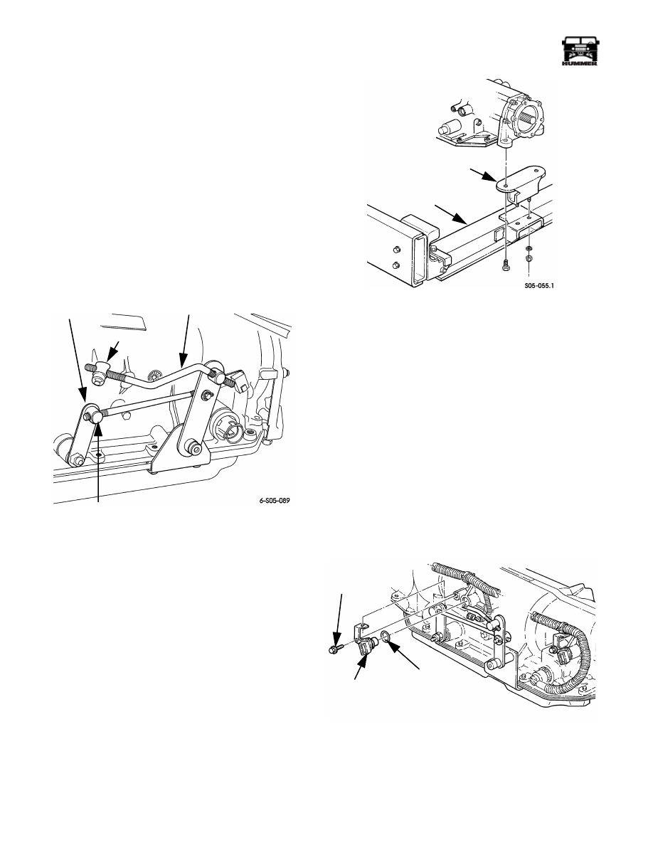
Figure 5-63: Transmission Shift Linkage
REAR MOUNT REPLACEMENT
1.
Support transmission with floor jack and wood blocks.
2.
Remove rear mount bolts/nuts and raise transmission
slightly.
3.
Remove rear mount from crossmember (Figure 5-64).
4.
Install mount on crossmember. Tighten attaching nuts to
65 lb-ft (88 N•m) torque.
5.
Lower transmission and install mount-to-adapter bolts.
6.
Tighten adapter bolts to 28 lb-ft (38 N•m) torque.
Figure 5-64: Rear Mount Replacement
TRANSMISSION INPUT SPEED SENSOR
REPLACEMENT
The input speed sensor is the forward sensor in the driver side
of the transmission. The rearward sensor is not used in this ap-
plication.
1.
Turn ignition switch to OFF position.
2.
Disconnect sensor wires.
3.
Remove bolt attaching sensor to case.
4.
Remove sensor with pull and twist motion.
5.
Remove O-ring seal from sensor (Figure 5-65).
6.
Lubricate new O-ring seal with ATF and install it on
sensor.
7.
Install sensor with push and turn motion.
8.
Install and tighten sensor bolt to 97 lb-in. (11 N•m) torque.
9.
Connect wires to sensor.
Figure 5-65: Speed Sensor Removal/Installation
TRUNNION
TRUNNION
SHIFT ROD
TRANSMISSION
SHIFT LEVER
REAR
CROSSMEMBER
REAR
MOUNT
INPUT SPEED
SENSOR
BOLT
O-RING

___________________________________________
Transmission/Transfer Case 5-149
®
05745159
TRANSFER CASE DESCRIPTION
Hummer vehicles are equipped with the New Process Gear,
model 242 transfer case. If you have questions about the trans-
fer case that are not answered by this section, you can call the
Transfer Case Hotline at 1-800-945-4327 for more informa-
tion.
The 242 is a full-time, 4-wheel drive transfer case with three
operating ranges plus a neutral position. Operating ranges are
High (H), Low (L), and High Lock (HL). Low range (L) posi-
tion provides a 2.72:1 reduction ratio for greater low speed,
off-road torque capability.
The transfer case extension, bearing retainer, rear case, and
front case are all aluminum castings. The front and rear output
drive sprockets are interconnected by a drive chain
(Figure 5-66). A differential in the transfer case, allows the
front/rear output shafts to run at differing speeds. This permits
full-time, 4-wheel drive operation in high range. The 242 is
also equipped with an internal-mount oil cooler.
Figure 5-66: Model 242 Transfer Case
FRONT RETAINER
LOW RANGE PLANETARY
RANGE SLEEVE
MODE
DIFFERENTIAL
DRIVE SPROCKET
SPEEDOMETER
TONE WHEEL
MAINSHAFT
EXTENSION
HOUSING
REAR
RETAINER
DRIVE CHAIN
REAR CASE
DRIVEN SPROCKET
FRONT OUTPUT SHAFT
YOKE
COOLER TUBE
FRONT CASE
ANNULUS
GEAR
INPUT
GEAR
SLEEVE
5-150
Transmission/Transfer Case
___________________________________________
®
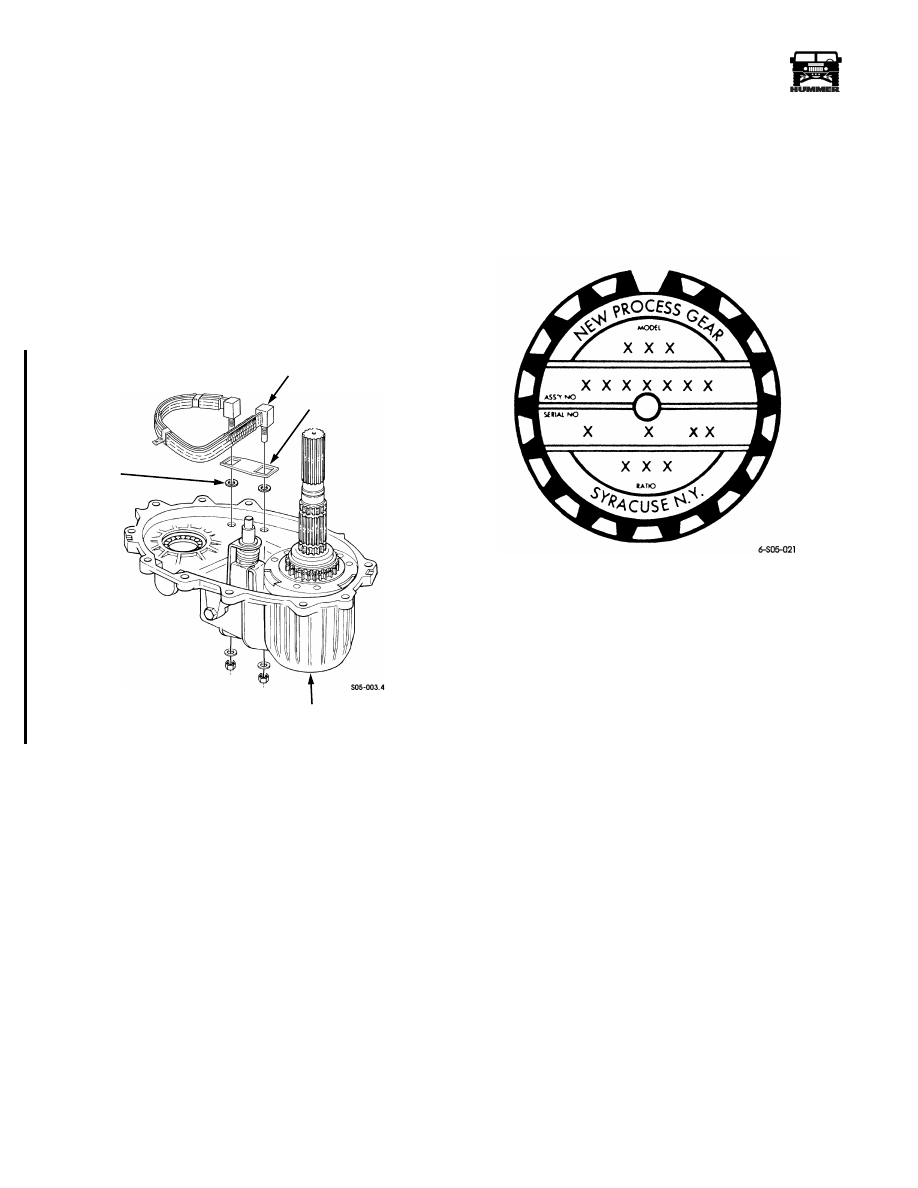
TRANSFER CASE OIL COOLER
The NP 242 used in Hummer vehicles is equipped with an in-
ternal oil cooler (Figure 5-67).
The cooler is mounted within the front case and secured by
nuts and washers. O-rings are used to seal the cooler inlet/out-
let tubes.
The cooler is interconnected to the transmission oil cooler cir-
cuit. However, transmission and transfer case oil are not inter-
mixed. In operation, oil from the transmission cooler flows
through the transfer case cooler. Heat from the transfer case oil
is transmitted to the transmission oil which is then conveyed to
the transmission cooler.
Figure 5-67: Oil Cooler Location
TRANSFER CASE IDENTIFICATION
An identification tag is attached to the rear case of each NP 242
transfer case (Figure 5-68). The tag provides the model num-
ber, assembly number, serial number, and low range ratio.
The serial number also represents the date of build. For exam-
ple, a serial number of 10-10-99 would represent a build date
of October 10, 1999.
Figure 5-68: Transfer Case I.D. Tag Information
RECOMMENDED LUBRICANT
Dexron III is the recommended lubricant for the NP 242. Use it
for topping off the fluid level and as replacement fluid for fluid
changes, or after overhaul. Dexron IIE can also be used for top-
ping off a low fluid level when Dexron III is not readily avail-
able.
Do not use friction modifiers or similar additives in the
NP 242. Use recommended lubricants only.
Transfer Case Fluid Level
Correct transfer case fluid level is to the lower edge of the fill
plug hole. Recommended fluid is Dexron III.
The vehicle must be on a level surface for an accurate fluid
level check. If the vehicle is raised on a hoist to check fluid
level, a drive-on style hoist is preferred. This type of hoist will
keep the vehicle level.
The fill plug is just above the drain plug in the rear case. Tight-
ening torque for the plug is 15-25 lb-ft (20-33 N•m).
FRONT CASE
O-RING
TRANSFER CASE INTERNAL OIL COOLER
SUPPORT
BRACKET
4-1-00
Нет комментариевНе стесняйтесь поделиться с нами вашим ценным мнением.
Текст