Hummer H1 (2002+). Manual — part 208
______________________________________________________
Electrical System 12-59
®
05745159
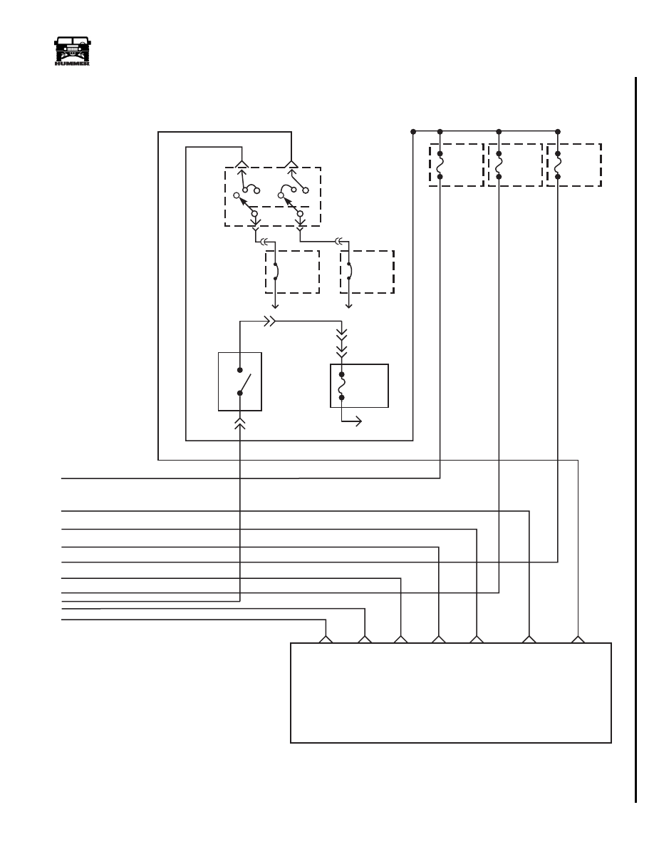
Figure 2-79: Lights Schematic (Sheet 2 of 2)
9-S12-007.1
20A
CB
MAXI
FUSE 2M
EXTERIOR
TO BATTERY
30A
CB
MAXI
FUSE 3M
EXTERIOR
TO BATTERY
15 WH
14 LB
15 WH
14 LB
20 RD
12 OR
13 TN
3 LB
80 WH
2 LG
21 GY
BUSS L1A
5 DG
9 YL
FUSE 3F
7.5 A
INTERIOR
FUSE 4F
7.5 A
INTERIOR
FUSE 6F
5 A
INTERIOR
HEADLIGHT FEED
TURN SIGNAL SWITCH
HIGH BEAM
LOW BEAM
LEFT TURN SIGNAL
RIGHT TURN SIGNAL
LEFT TURN REAR
RIGHT TURN REAR
C1-67
C1-51
FUSE 6F
5 A
INTERIOR
BACKUP
LIGHT
SWITCH
C2-27
C1-43
HOT in RUN
and START
298 BR
140 OR
MASTER
LIGHT
SWITCH
4-1-00
12-60
Electrical System
_______________________________________________________
®
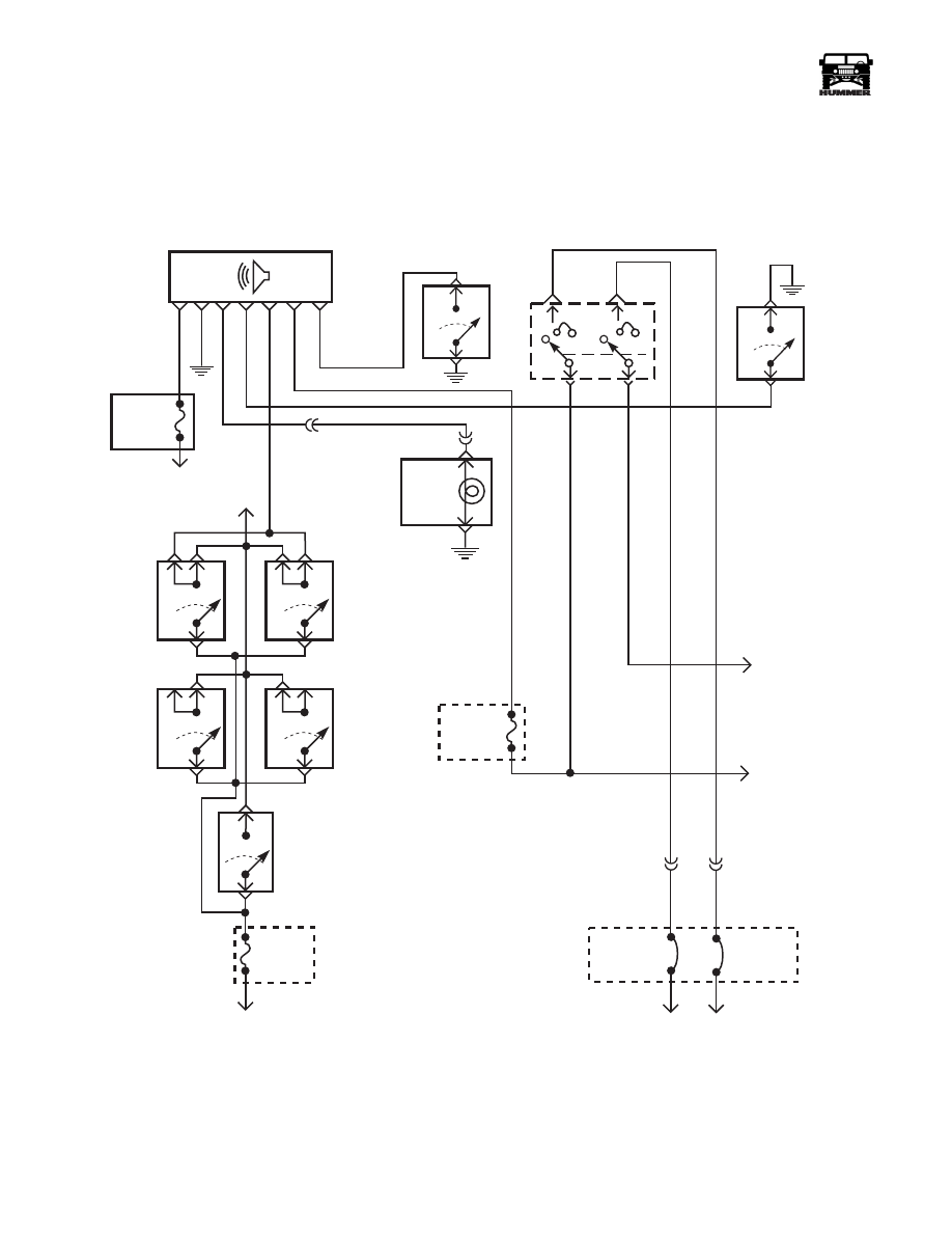
Figure 2-80: Key/Headlight Chime Schematic
FUSE
7F
5 AMP
INTERIOR
FUSE
1G
5 AMP
INTERIOR
KEY, HEADLIGHT, SEATBELT CHIME
G4
59 BK
640 BR
450 PK
85 GY
159 WH
183 TN
158 BK
KEY SWITCH
(STEERING COLUMN)
G4
59 BK
SEAT BELT
SWITCH
85 GY
38 RD
95 YL
MASTER LIGHT SWITCH
TO
DOME
LIGHT
FUSE
5H
15 AMP
INTERIOR
TO BATTERY
DOOR
SWITCHES
RF
LF
RR
LR
HMCS
ONLY
CARGO
DOOR
G
C1 C3
30 AMP
CB
MAXI FUSE
3M ENGINE
TO BATTERY
C1 G7
C1-51
14 LB
TO TURN
SIGNAL
SWITCH/
DIMMER
15 WH
TO
PARKING
LIGHTS
FUSES
20 AMP
CB
MAXI FUSE
2M ENGINE
SEAT
BELT
RIGHT SIDE
WARNING
LIGHT-1P
TO
IGN
9-S12-003
4-1-00
______________________________________________________
Electrical System 12-61
®
05745159
HORN
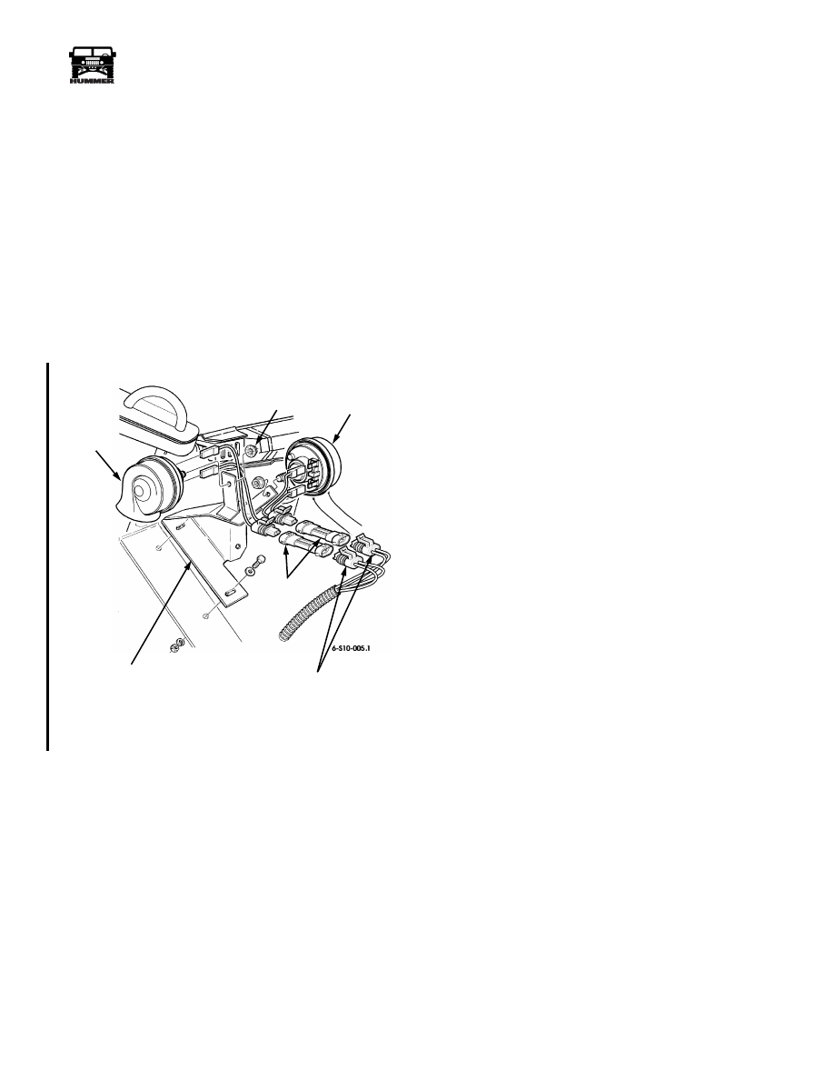
Horn Replacement
Removal
1.
Remove harness connectors and adapters from horn.
2.
Remove nut and horn from mounting bracket
(Figure 2-81).
NOTE: Overtightening horn mounting nut will distort the horn
bellows and result in an “off-key” horn tone.
Installation
1.
Secure horns to mounting bracket with nuts.
2.
Plug harness connectors and adapters into horns.
Figure 2-81: Horn and Horn Mounting Bracket
Replacement
Horn Mounting Bracket Replacement
Removal
1.
Remove two horns.
2.
Remove bolts, washers, lockwashers, nuts, and horn
mounting bracket from airlift bracket (Figure 2-81).
Installation
1.
Secure horn mounting bracket to airlift bracket with bolts,
washers, lockwashers, and nuts (Figure 2-81).
2.
Install two horns.
HORN
MOUNTING
BRACKET
HARNESS CONNECTORS
NUT
HORN
ADAPTERS
4-1-00

12-62
Electrical System
_______________________________________________________
®
Horns Inoperative
Step
Action
Value Yes
No
1
Locate the horn assemblies under the hood.
Disconnect the harness from the horn assemblies.
With a DVOM check the black wires (CKT 58) for
resistance to ground. Do both wires meet with
specifications?
<.2
Ω
Go to step 2.
Repair the open
or bad connection
on CKT 58
between the horn
assemblies and
G2.
2
With a DVOM back probe the white wires on the
horn assemblies and check for voltage when the
horn button is pushed. Is the specified voltage
present?
12v
Replace the horn
assemblies.
Go to step 3.
3
Remove the horn relay from the exterior fuse box.
With a DVOM check resistance between the relay
cavity 1F and the white wire (CKT 6) on the horn
assembly. Does the resistance meet the
specifications?
<.2
Ω
Go to step 4.
Repair the open
or bad connection
in CKT 6
between the horn
relay and the
horn assembly.
4
With a DVOM check for voltage in cavities 3E
and 1E of the exterior fuse box. Is the specified
voltage present?
12v
Go to step 5.
Repair the open
or bad connection
in CKT 7
between the horn
relay and the
exterior fuse box.
5
With a DVOM check the resistance to ground on
cavity 3F, of the exterior fuse box, when the horn
switch is pressed. Does the resistance meet the
specifications?
<.2
Ω
Replace the
horn relay.
Go to step 6.
6
Gain access to connector C39. With a DVOM
back probe cavity C on connector 39. Activate the
horn switch and watch the resistance on the meter.
Does the resistance meet the specifications?
<.2
Ω
Repair the open
or bad connection
on CKT 1
between the horn
switch and the
horn relay.
Replace the turn
signal assembly.
4-1-00
Нет комментариевНе стесняйтесь поделиться с нами вашим ценным мнением.
Текст