Hummer H1 (2002+). Manual — part 280

_____________________________________________________
PCM/Tech 1 Scan Tool 53
®
05745159
DTC P0221 - Accelerator Pedal Position (APP) Sensor 2 Circuit Performance
Step
Action
Value(s)
Yes
No
1
Important:
Before clearing DTC(s) use the scan tool “Capture Info” to
record Freeze Frame and Failure Record for reference, as data will be lost
when “Clear Info” function is used.
Was the “On-Board Diagnostic (OBD) System Check” performed?
—
Go to Step 2. Go to OBD Sys-
tem Check.
2
1. Ignition “ON”, engine “OFF”.
2. With the throttle closed, observe APP voltages on the scan tool.
Are APP at specified values?
.45-.95v
4.0-4.5v
3.6-4.0v
Go to Step 3. Go to Step 4.
3
DTC is intermittent. If no additional DTCs are stored, refer to “Diagnostic
Aids”. If additional DTCs were stored, refer to those chart(s).
—
Go to the
applicable
DTC table.
Go to
Diagnostic
Aids.
4
1. Disconnect the APP sensor electrical connector.
2. Ignition “ON”, engine “OFF”.
3. With J–39200 connected to ground, probe APP sensor 5 volt reference
circuits at APP harness terminals “G”, “D” and “E”.
Is voltage at the specified value on all circuits?
4.75v
Go to Step 5. Go to Step 6.
5
1. Ignition “ON”, engine “OFF”.
2. With a test light connected to B+, probe APP sensor ground circuits at
the APP sensor harness terminals “A”, “B” and “J”.
Is the test light “ON” (all circuits)?
—
Go to Step 9.
Go to Step 8.
6
1. Ignition “OFF”
2. Disconnect the PCM and check the 5 volt reference circuit for an open or
short to ground.
3. If the 5 volt reference circuit is open or shorted to ground, repair it as
necessary.
Was the 5 volt reference circuit open or shorted to ground?
—
Go to Step 11.
Go to Step 7.
7
Check the 5 volt reference circuit for a poor connection at the PCM and
replace terminal if necessary.
Did the terminal require replacement?
—
Go to Step 11. Go to Step 10.
8
1. Ignition “OFF”
2. Disconnect the PCM and check for an open sensor ground circuit to the
PCM.
3. If problem is found, repair as necessary.
Was APP sensor ground circuit open?
—
Go to Step 11. Go to Step 10.
9
Replace the APP module.
Is Action complete?
—
Go to Step 11.
—
10
Replace the faulty PCM. Notice: If the PCM is faulty, the new PCM must
be programmed. Go to PCM replacement and programming procedures.
Is the action complete?
—
Go to Step 10.
—
11
1. Using the Scan Tool, select “DTC”, “Clear Info”.
2. Start engine and idle at normal operating temperature.
3. Select “DTC”, “Specific”, then enter the DTC number which was set.
4. Operate vehicle within the conditions for setting this DTC as specified in
the supporting text.
Does the Scan Tool indicate that this diagnostic Ran and Passed?
—
Go to Step 12.
Go to Step 2.
12
Using the Scan Tool, select “Capture Info”, “Review Info”.
Are any DTCs displayed that have not been diagnosed?
—
Go to the
applicable
DTC table
System OK
54
PCM/Tech 1 Scan Tool
_____________________________________________________
®
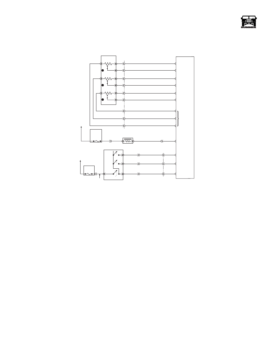
DTC P0222 Accelerator Pedal Position (APP)
Sensor 2 Circuit Low Voltage
Circuit Description
The Accelerator Pedal Position (APP) module provides a volt-
age signal that changes relative to accelerator position. There
are three sensors located within the APP module that are scaled
differently. This is a type C DTC.
Conditions for Setting the DTC
• Voltage is less than .25 volts on APP 2 sensor.
• Conditions met for 2 seconds.
Action Taken When the DTC Sets
• The input from APP 2 sensor is ignored.
• A current and history DTC will set but it will not turn on
the “Service Throttle Soon” lamp.
• The throttle will operate normally as long as there is
only one sensor malfunction present. If two different
APP sensors have a malfunction, the “Service Throttle
Soon” lamp will light and the PCM will limit power. If
three APP sensors have a malfunction present, the “Ser-
vice Throttle Soon” lamp will light and the PCM will
only allow the engine to operate at idle.
Conditions for Clearing the MIL/DTC
• A History DTC will clear when forty consecutive
warm-up cycles that the diagnostic does not fail (coolant
temperature has risen 5°C (40°F) from start up coolant
temperature and engine coolant temperature exceeds
71°C (160°F) that same ignition cycle).
• Use of a Scan Tool
Diagnostic Aids
A scan tool reads APP 2 position in volts and should read about
4.5 volts with throttle closed and ignition “ON” or at idle. Volt-
age should decrease at a steady rate as throttle is moved toward
Wide Open Throttle (WOT). An open or short to ground in
CKT 996 or 993 will result in a P0222. Refer to Section 2 for
“Intermittents”. Scan APP 2 sensor while depressing accelera-
tor pedal with engine stopped and ignition “ON”, Display
should vary from about 4.5 volts when throttle was closed to
about 1.5 volts when throttle is held at Wide Open Throttle
(WOT) position.
Test Description
Number(s) below refer to the circled number(s) on the diagnos-
tic table.
2. This step determines if P0222 is the result of a hard failure or
an intermittent condition.
3. This step checks the PCM and wiring.
FUSE 5C
10AMP
INTERIOR
FUSE 3A
10 AMP
EXTERIOR
ON/
OFF
SET
COAST
RESUME
ACCEL
HOT IN RUN
AND START
HOT IN RUN
AND START
A
29
42
37
C1
C29-A11
C29-B11
C27-D10
C28-D14
C28-C2
C27-D12
C27-D3
C27-D4
C27-D6
C29-B2
C29-B1
C27-C5
C29-A12
C5-D3
C5-A4
A
B
154 TN
151 GY
152 DB
153 LG
ON / OFF
SIGNAL
SET
COAST
SIGNAL
RESUME
ACCEL
SIGNAL
WASTEGATE
SOLENOID
CONTROL
5 VOLT
REFERENCE
APP 3
SIGNAL
GROUND
APP 1
SIGNAL
GROUND
GROUND
D
B
C
A
G
E
F
J
K
3
1
2
C1
22
20
14
15
60
32
53
17
44
720 TN
717 WH
723 YL
724 DG
725 GY
718 DB
719 BR
721 LB
722 PP
ACCELERATIOR
PEDAL POSITION
SENSOR
POWERTRAIN
CONTROL
MODULE
(PCM)
APP 2
SIGNAL
9-S12-055
B
C
D
295 BR
YL
GRN
RD

_____________________________________________________
PCM/Tech 1 Scan Tool 55
®
05745159
DTC P0222 - Accelerator Pedal Position (APP) Sensor 2 Circuit Low Voltage
Step
Action
Value(s)
Yes
No
1
Important:
Before clearing DTC(s) use the scan tool “Capture Info”.
Was the “On-Board Diagnostic (OBD) System Check” performed?
—
Go to Step 2. Go to OBD Sys-
tem Check.
2
1. Ignition “ON”, engine “OFF”.
2. With the throttle closed, observe APP 2 voltages on the scan tool.
Is APP 2 voltage less than or equal to the specified value?
.25v
Go to Step 3. Go to Step 4.
3
DTC is intermittent..
Are additional DTCs stored?
—
Go to the
DTC table.
Go to
Diagnostic
Aids.
4
1. Disconnect the APP sensor electrical connector.
2. Jumper APP 2 5 volt reference circuit and the APP 2 signal together at
the APP sensor harness connector.
3. Observe the APP 2 voltage on the Scan Tool.
Is APP 2 voltage greater than the specified value?
4.75v
Go to Step 10. Go to Step 5.
5
1. Connect a test light between B+ and the APP 1 sensor signal circuit at
the APP sensor harness connector.
2. Observe the APP 2 voltage on the Scan Tool.
Is APP 2 voltage greater than the specified value?
4.75v
Go to Step 6.
Go to Step 8.
6
1. Ignition “OFF”.
2. Disconnect the PCM and check the 5 volt reference circuit for an open or
short to ground.
3. If the 5 volt reference circuit is open or shorted to ground, repair as nec-
essary.
Was the 5 volt reference circuit open or shorted to ground?
—
Go to Step 12.
Go to Step 7.
7
Check the 5 volt reference circuit for a poor connection at the PCM and
replace terminal if necessary. Did the terminal require replacement?
—
Go to Step 12. Go to Step 11.
8
1. Ignition “OFF”.
2. Disconnect PCM, and check APP 2 signal circuit for short to ground.
3. Repair as necessary.
Was APP 2 signal circuit open or shorted to ground?
—
Go to Step 12.
Go to Step 9.
9
Check the APP 2 sensor signal circuit for a poor connection at the PCM and
replace terminal if necessary. Did the terminal require replacement?
—
Go to Step 12. Go to Step 11.
10
Replace the APP module.
Is Action complete?
—
Go to Step 12.
—
11
Replace the faulty PCM.
Is the action complete?
—
Go to Step 12.
—
12
1. Using the Scan Tool, select “DTC”, “Clear Info”.
2. Start engine and idle at normal operating temperature.
3. Select “DTC”, “Specific”, then enter the DTC number which was set.
4. Operate vehicle within the conditions for setting this DTC as specified in
the supporting text.
Does the Scan Tool indicate that this diagnostic Ran and Passed?
—
Go to Step 13.
Go to Step 2.
13
Using the Scan Tool, select “Capture Info”, “Review Info”.
Are any DTCs displayed that have not been diagnosed?
—
Go to the
DTC table
System OK
56
PCM/Tech 1 Scan Tool
_____________________________________________________
®
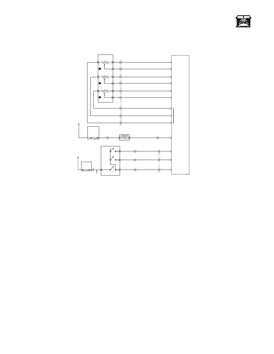
DTC P0223 Accelerator Pedal Position (APP)
Sensor 2 Circuit High Voltage
Circuit Description
The Accelerator Pedal Position (APP) module provides a volt-
age signal that changes relative to accelerator position. There
are three sensors located within the APP module that are scaled
differently. This is a type C DTC.
Conditions for Setting the DTC
• Voltage is greater than 4.75 volts on APP 2.
• Conditions met for 2 seconds.
Action Taken When the DTC Sets
• The input from APP 2 sensor is ignored.
• A current and history DTC will set but it will not turn on
the “Service Throttle Soon” lamp. The throttle will op-
erate normally as long as there is only one malfunction
present. If two different APP sensors have a malfunc-
tion, the “Service Throttle Soon” lamp will light and the
PCM will limit power. If three APP sensors have a mal-
function present, the “Service Throttle Soon” lamp will
light and the PCM will only allow the engine to operate
at idle.
Conditions for Clearing the MIL/DTC
• A History DTC will clear when forty consecutive
warm-up cycles that the diagnostic does not fail (coolant
temperature has risen 5°C (40°F) from start up coolant
temperature and engine coolant temperature exceeds
71°C (160°F) that same ignition cycle).
• Ignition must be cycled if P1125 is also set.
• Use of a Scan Tool
Diagnostic Aids
A scan tool reads APP 2 position in volts and should read about
4.5 volts with throttle closed and ignition “ON” or at idle. Volt-
age should decrease at a steady rate as throttle is moved toward
Wide Open Throttle (WOT). Also, 90% pedal travel is accept-
able for correct APP operation. Refer to Section 2 for “Inter-
mittents”. Scan APP 2 signal while depressing accelerator
pedal with engine stopped and ignition “ON”. Display should
vary from about 4.5 volts when throttle is closed to about 1.5
volts when throttle is held at Wide Open Throttle (WOT) posi-
tion. Its possible P1125 will set along with P0223 if the signal
circuit is open.
Test Description
Number(s) below refer to the number(s) on the diagnostic ta-
ble.
2. This step determines if P0223 is a hard failure or an intermit-
tent condition.
3. This step will check for an open in the ground circuit.
FUSE 5C
10AMP
INTERIOR
FUSE 3A
10 AMP
EXTERIOR
ON/
OFF
SET
COAST
RESUME
ACCEL
HOT IN RUN
AND START
HOT IN RUN
AND START
A
29
42
37
C1
C29-A11
C29-B11
C27-D10
C28-D14
C28-C2
C27-D12
C27-D3
C27-D4
C27-D6
C29-B2
C29-B1
C27-C5
C29-A12
C5-D3
C5-A4
A
B
154 TN
151 GY
152 DB
153 LG
ON / OFF
SIGNAL
SET
COAST
SIGNAL
RESUME
ACCEL
SIGNAL
WASTEGATE
SOLENOID
CONTROL
5 VOLT
REFERENCE
APP 3
SIGNAL
GROUND
APP 1
SIGNAL
GROUND
GROUND
D
B
C
A
G
E
F
J
K
3
1
2
C1
22
20
14
15
60
32
53
17
44
720 TN
717 WH
723 YL
724 DG
725 GY
718 DB
719 BR
721 LB
722 PP
ACCELERATIOR
PEDAL POSITION
SENSOR
POWERTRAIN
CONTROL
MODULE
(PCM)
APP 2
SIGNAL
9-S12-055
B
C
D
295 BR
YL
GRN
RD
Нет комментариевНе стесняйтесь поделиться с нами вашим ценным мнением.
Текст