Hummer H1 (2002+). Manual — part 174
_____________________________________________________________________
Body 10-67
®
05745159
Soft Top Mounting Components and
Accessories Replacement
NOTE:
The following removal and installation
instructions include replacement of all soft top mounting com-
ponents and accessories. Use only the applicable steps for re-
placing specific components.
Removal
1.
Remove four-passenger soft top, tonneau cover, or station
wagon soft top, if applicable. Refer to the owner’s manual
for proper procedure.
2.
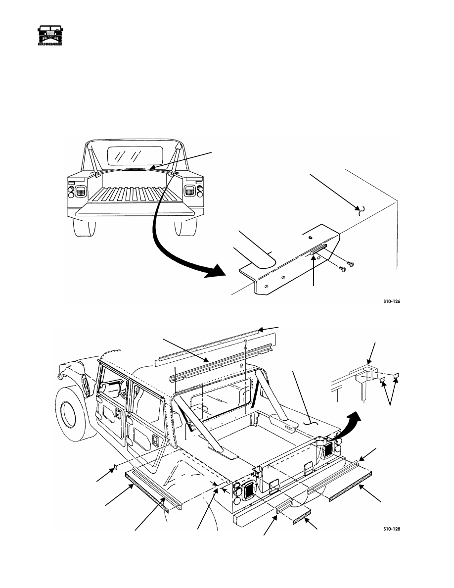
Remove tonneau cover wood bow from two retainer
brackets (Figure 10-130).
3.
Remove four screws and two bow retainer brackets from
wheelhouses.
Figure 10-130: Tonneau Cover Wood Bow Removal
Figure 10-131: Velcro Strip and Patch Removal
TONNEAU COVER
WHEELHOUSE
BOW RETAINER
WOOD BOW
BRACKET
TONNEAU/REAR CURTAIN EXTRUSION
VELCRO STRIP
TAILGATE CHAIN
VELCRO PATCH
43 IN. (109 cm)
TONNEAU EXTRUSION
43 IN. (109 CM)
9 IN. (23 CM)
9 IN. (23 CM)
41 IN. (104 CM)
41 IN. (104 CM)
VELCRO PATCH
ATTACHMENT CHANNEL
VELCRO STRIP
2 IN. (5 CM)
FROM EDGE
VELCRO STRIP
VELCRO STRIP
TONNEAU EXTRUSION
TONNEAU EXTRUSION
WHEEL HOUSE
10-68
Body
______________________________________________________________________
®
4.
Remove velcro strips and patches from tonneau area
(Figure 10-131).
NOTE:
Perform steps five and six for both sides of the vehi-
cle. The left side is shown.
5.
Remove 41 in. (104 cm) tonneau extrusion from side of
wheelhouse.
6.
Remove 9 in. (23 cm) tonneau extrusion from rear of
wheelhouse.
7.
Remove 43 in. (109 cm) tonneau extrusion from tailgate.
8.
Remove five screws, lockwashers, four self-tapping
screws, and tonneau/rear curtain extrusion from body.
9.
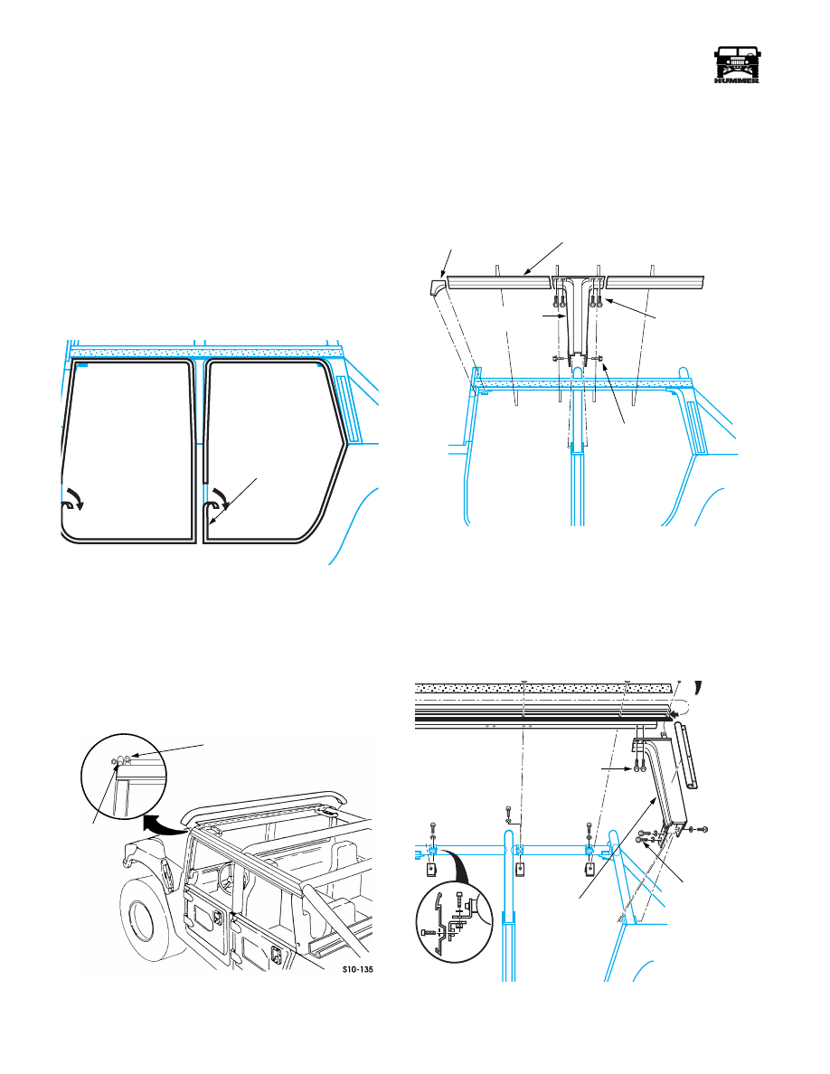
Remove front and rear inner door seals (Figure 10-132).
Figure 10-132: Door Seal Removal
NOTE:
This procedure is written for the left side of the vehicle
only. Duplicate steps are necessary to service the right hand
side.
10. Remove soft top from the vehicle.
11. Remove D-strip seal from windshield frame. Do not
remove P-strip seal (Figure 10-133).
Figure 10-133: D-Strip Seal Removal
12. Remove 12 screws securing front attachment rail to the
top of the windshield frame, and remove rail.
13. Slide velcro strips in the two side rails rearward to remove,
set aside.
14. Remove four screws securing the B-pillar cover to the
bottom of the H-rail.
Figure 10-134: B-Pillar Cover Removal
15. Remove two bolts securing B-pillar cover to the B-pillar.
Remove the B-pillar cover.
16. Remove the three screws securing the C-pillar cover to the
H-rail.
17. Remove the four bolts securing the lower inner and outer
bracket on the C-pillar cover. Remove the cover.
Figure 10-135: C-Pillar Cover Removal
INNER DOOR SEAL
8-S10-002
P-STRIP SEAL
D-STRIP SEAL
UPPER
LOWER
H-RAIL
FILLER PIECE
B-PILLAR
COVER
RETAINING
SCREWS
RETAINING
SCREWS
8-S10-003
C-PILLAR
UPPER
LOWER
RETAINING
SCREWS
COVER
RETAINING
SCREWS
8-S10-004
_____________________________________________________________________
Body 10-69
®
05745159
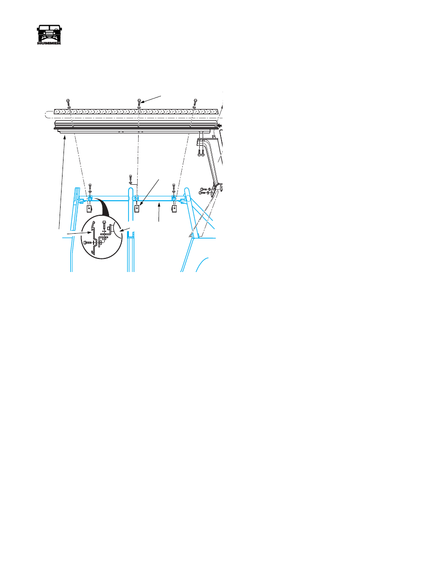
18. Remove three screws securing H-Rail to the vehicle safety
cage. Leave the L brackets on the safety cage unless the
cage is going to be replaced, remove the H-rail.
Figure 10-136: H-Rail Removal
NOTE:
While removing the H-rail, note where sealer is placed
so during installation, the sealer can be duplicated
Installation
1.
Install L brackets to support structure so the bend is to the
bottom and the brackets are adjusted upward as far as they
could go. Leave the brackets finger tight to ease installa-
tion of other components and adjustment later in the pro-
cedure.
2.
Using a bolt and washer, install the threaded L-brackets
onto the H-rail so the bend is upwards. Tighten bolt.
3.
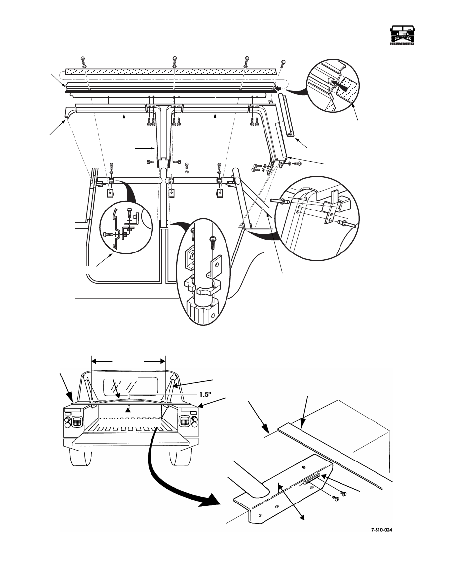
Put foam tape on the top mating surface of the C-pillar
cover, and place the rear extrusion against the bottom
surface of the H-rail. Install three screws (Figure 10-137).
4.
Put foam tape on the top edge of the B-pillar cover. Place
the cover against the bottom edge of the H-rail and tighten
four upper screws (Figure 10-137).
5.
Apply sealer to bottom of B- and C-pillar covers.
6.
Install the H-rail onto the support structure. Place the L-
brackets installed on the H-rail under the L-brackets on the
support structure. Tighten screws when installed.
7.
Install lower fasteners in B-pillar cover. Do not tighten
(Figure 10-137).
8.
Install lower fasteners in C-pillar cover. Do not tighten
(Figure 10-137).
9.
Adjust H-rail and extrusions so seams are flush, tighten
fasteners.
10. Install front upper corner filler piece with two rivets and
sealer (Figure 10-137).
11. Clean excess sealer from mating surfaces.
12. Install new inner door seals. Check door to frame fit and
adjust structure if necessary.
13. Install rail and P-seal on top of windshield with (12)
screws.
14. Install new rubber D-seal between P-seal and the rail.
15. Install the soft top and secure.
NOTE:
Clean all surface residue with a tape adhesion pro-
moter before installing extrusions with 2 sided tape.
16. Secure tonneau/rear curtain extrusion to body with five
lockwashers, capscrews, and four self-tapping screws. Use
windshield sealer between the extrusion and the body
(Figure 10-131).
17. Install 43 in. (109 cm) tonneau extrusion on tailgate.
18. Secure 9 in. (23 cm) tonneau extrusion to rear of
wheelhouse.
19. Secure 41 in. (104 cm) tonneau extrusion to side of
wheelhouse, 2 in. (5 cm) from rear corner edge of
wheelhouse.
20. Install velcro strips in extrusions.
21. Install one velcro patch on each wheelhouse side and two
velcro patches on each tailgate chain attachment channel.
22. Secure two bow retainer brackets to wheelhouses with
four screws (Figure 10-138).
23. Leak check the vehicle and add sealer where necessary.
24. Test drive vehicle and check for wind noise.
CAUTION: The ideal crown height of the bow is shown. If
there is excessive crowning of the bow, cut the end of the wood
bow with a saw to reduce the crown. Do not cut more than 0.25
in. (6 mm) at a time, or the bow may become too short.
25. Measure and record the distance across the cargo bed,
between each rear support bar brace. Add 0.25 to 0.50 in.
(6 to 13 mm) to this dimension and mark and cut the wood
bow to this dimension.
26. Position wood bow in two retainer brackets. Lay a straight
edge across the wheel houses as shown (Figure 10-138).
The ideal bow height is 1.5 in. from the straight edge to
the bow crown.
27. Install the four-passenger soft top, tonneau cover, and
slant-back soft top or station wagon soft top, if applicable.
Refer to the owner’s manual.
H-RAIL SCREWS (3)
L-BRACKETS
H-RAIL
SUPPORT STRUCTURE
8-S10-004
10-70
Body
______________________________________________________________________
®
Figure 10-137: Rail and Support Structure Locations
Figure 10-138: Bow Retainer Bracket Installation
8-S10-001
VELCRO
REAR, SIDE, P-CHANNEL
H-RAIL
B-PILLAR
COVER
C-PILLAR COVER
SUPPORT STRUCTURE
FRONT
FILLER PIECE
FILLER
FILLER
B-PILLAR COVER
LOWER BRACKET
INSTALLATION
MEASURE
REAR SUPPORT
BOW
MEASURE DISTANCE BETWEEN
REAR SUPPORT
RETAINER
BRACKET
INNER FACE OF
BAR BRACES
BAR BRACE
DISTANCE
WHEEL HOUSE
IDEAL BOW HEIGHT
STRAIGHTEDGE
WOOD BOW
STRAIGHTEDGE
Нет комментариевНе стесняйтесь поделиться с нами вашим ценным мнением.
Текст