Hummer H1 (2002+). Manual — part 85
___________________________________________
Transmission/Transfer Case 5-139
®
05745159
TORQUE CONVERTER/FLEXPLATE/
CONVERTER SEAL REPLACEMENT
1.
Remove transmission as described in this section.
2.
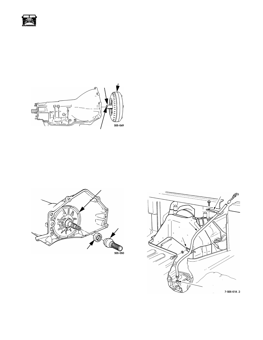
Remove torque converter from transmission (Figure 5-42).
3.
Remove oil seal from pump. Use standard hook tool to
pull seal.
Figure 5-42: Torque Converter Removal/Installation
4.
If flexplate is to be replaced, remove attaching bolts and
remove driveplate.
5.
Position new flexplate on crankshaft flange. Apply 1-2
drops of Loctite 242 to flexplate bolt threads. Then install
and tighten bolts to 65 lb-ft (88 N•m) torque.
Figure 5-43: Oil Pump Seal Installation
6.
Install converter seal with tool J–38694 (Figure 5-43).
7.
Install torque converter. Be sure drive lugs on pump gear
are engaged in drive slots of converter hub (Figure 5-42).
8.
Install transmission as described in this section.
NOTE:
Converter will be recessed in housing when installed
completely and will turn freely when transmission is installed
on engine.
TRANSMISSION REMOVAL
1.
Remove console and engine cover.
2.
Remove bolts attaching transmission fill tube to heat
shield and intake manifold (Figure 5-44). Then remove fill
tube from transmission case. Cover fill tube bore in case to
prevent dirt entry.
3.
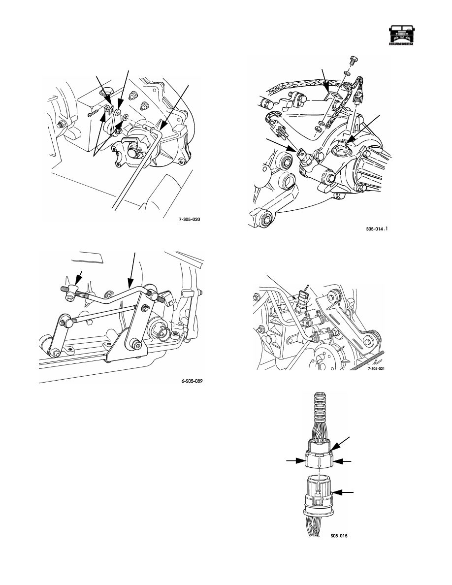
Disconnect transfer case shift rod at operating lever
(Figure 5-45).
4.
Disconnect transmission shift rod trunnion from shift
control arm (Figure 5-46).
5.
Disconnect speed sensor and lock indicator switch wires at
rear of transfer case (Figure 5-47). Then disconnect range
switch at front of transfer case (Figure 5-48).
6.
Remove clamps securing wire harness to transfer case and
transmission.
7.
Disconnect vent lines at transmission and transfer case.
8.
Disconnect transmission harness at case connector by
squeezing both lock tabs of harness connector, and pulling
it straight out of case connector.
CAUTION:
Do not pull, twist, pry, or rotate the harness con-
nector in an attempt to remove it. This action can damage the
connector body, pin terminals and solder joints. Release only
by squeezing the lock tabs (Figure 5-49).
9.
Disconnect harness wires at transmission input speed
sensor (Figure 5-50).
Figure 5-44: Fill Tube Attachment
HUB
SLOTS
TORQUE
CONVERTER
OIL PUMP
CONVERTER SEAL
SEAL
J–38694
INSTALLER
FILL TUBE
SEAL
BRACKET
BRACKET
FILL
TUBE
5-140
Transmission/Transfer Case
___________________________________________
®
Figure 5-45: Shift Rod Attachment
Figure 5-46: Transmission Shift Rod and Trunnion
Figure 5-47: Vehicle Speed Sensor and Switch
Harness Connections
Figure 5-48: Range Indicator Connection
Figure 5-49: Releasing Transmission Case Harness
Connectors
TRANSFER
CASE
SHIFT ROD
OPERATING
LEVER
FLAT
WASHERS
WAVY
WASHER
TRUNNION
SHIFT ROD
BRACKET
VEHICLE
SPEED
SENSOR
LOCK
INDICATOR
SWITCH
RANGE
INDICATOR SWITCH
LOCK TAB
(SQUEEZE)
HARNESS
CONNECTOR
CASE
CONNECTOR
LOCK TAB
(SQUEEZE)
___________________________________________
Transmission/Transfer Case 5-141
®
05745159
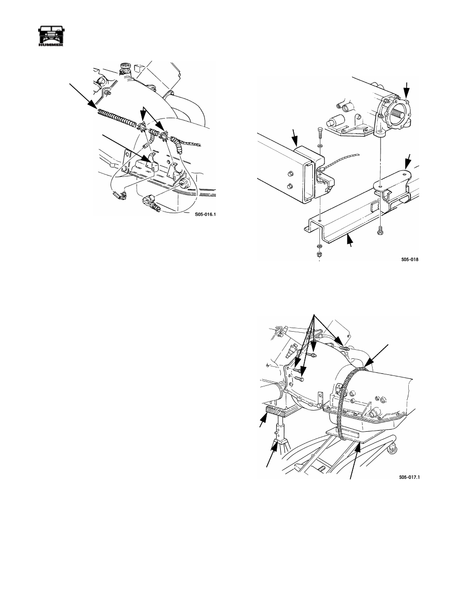
Figure 5-50: Speed Sensor Connections
10. Remove transmission harness from retaining clips.
11. Disconnect front propeller shaft and remove rear propeller
shaft.
12. Remove exhaust crossover pipe and disconnect exhaust
mounting at the transfer case.
13. Remove converter housing covers.
14. Support engine with jack stand and wood block positioned
under oil pan.
15. Support transmission with transmission jack.
16. Remove transfer case guide cable.
17. Disconnect cooler lines at transfer case and transmission.
18. Remove nuts attaching transfer case to transmission
adapter and remove transfer case with aid of helper.
19. Remove bolts attaching transmission mount to
transmission adapter (Figure 5-51). Then remove bolts
attaching crossmember to frame brackets and remove
crossmember.
20. Secure safety chain around transmission and jack
(Figure 5-52).
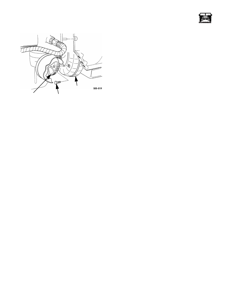
21. Remove bolts attaching torque converter to driveplate
flywheel (Figure 5-53).
22. Remove bolts and studs attaching transmission to engine
(Figure 5-52).
23. Move transmission rearward until clear of engine. Then
use C-clamp or strap attached to housing to hold converter
in place.
24. Move transmission from under vehicle.
Figure 5-51: Transmission Rear Mounting
Figure 5-52: Transmission Removal/Installation
INPUT
SPEED
SENSOR
HARNESS
CLIPS
TRANSMISSION
WIRING
HARNESS
TRANSMISSION
ADAPTER
FRAME
BRACKET
TRANSMISSION
MOUNT
CROSSMEMBER
STUDS
SAFETY CHAIN
TRANSMISSION
JACK
JACK
STAND
WOOD
BLOCK
5-142
Transmission/Transfer Case
___________________________________________
®
Figure 5-53: Torque Converter-To-Flexplate Bolt
Locations
TRANSMISSION INSTALLATION
CAUTION:
If the transmission was replaced, or repaired to
correct a problem that generated metal and clutch disc parti-
cles, the transmission cooler and lines must be thoroughly
flushed and the torque converter replaced. This is necessary to
avoid recontaminating and damaging the transmission.
1.
Mount transmission on transmission jack and secure trans-
mission with safety chain (Figure 5-52).
2.
Tilt transmission converter housing upward slightly to
help retain converter during installation.
3.
Smooth converter hub with 320-380 grit emery to remove
burrs or sharp edges. Clean hub thoroughly afterward.
Hub must be smooth to avoid damaging converter seal
during installation.
4.
Lubricate converter hub and converter seal with
transmission fluid. Then install converter. Be sure
converter is fully seated in pump before proceeding.
5.
Move transmission into position and align transmission
converter housing with engine block dowels. Slide
transmission forward and into place. Be sure converter
pilot is seated in crankshaft and that transmission is
aligned on dowels. Install one or two studs or bolts to hold
transmission in place.
6.
Install and tighten transmission attaching stud and bolts to
35 lb-ft (47 N•m) torque.
7.
Apply one or two drops of Loctite 242 to threads of
attaching bolts. Then install and tighten bolts to 32 lb-ft
(43 N•m) torque.
8.
Install converter housing covers.
9.
Install transfer case. Tighten attaching nuts to 30 lb-ft (41
N•m) torque.
10. Install rear crossmember and secure transmission mount to
adapter. Tighten adapter-to-mount bolts to 65 lb-ft (88
N•m) torque. Tighten crossmember-to-frame bracket bolts
to 90 lb-ft (122 N•m) torque.
11. Connect oil cooler lines to transmission and transfer case.
Be sure lines are properly secured in clamps and brackets.
12. Connect vent lines to transmission and transfer case.
13. Connect transmission harness to transmission case
connector. Be sure harness connector is fully seated and
snaps into place.
14. Connect wires to transmission input sensor.
15. Connect wires to transfer case range and lock switches,
and to speed sensor.
16. Attach transmission shift rod to arm of control assembly.
Then connect transfer case shift rod to range lever on
transfer case.
17. Install transfer case guide cable.
18. Check and top off transfer case fluid if necessary.
19. Install starter motor.
20. Install exhaust pipes, muffler, and catalytic converter.
21. Install front and rear propeller shafts.
22. Install transmission fill tube and dipstick. Replace fill tube
seal if worn, cut, or distorted.
23. Install engine cover and console.
24. Add four quarts (3.7 liters) of Dexron III to transmission.
25. Drive vehicle long enough to bring transmission fluid to
normal operating temperature.
26. Check transmission fluid level. Add fluid in small
increments to avoid over filling. Correct hot level is in, or
to top of crosshatch area on dipstick with engine idling
and transmission in Park.
TORQUE
CONVERTER
CONVERTER
BOLT (6)
DRIVEPLATE
(FLYWHEEL)
Нет комментариевНе стесняйтесь поделиться с нами вашим ценным мнением.
Текст