Hummer H1 (2002+). Manual — part 200
______________________________________________________
Electrical System 12-27
®
05745159
Alternator Assembly
1.
Install bearing on rotor shaft. Seat bearing against shoul-
der (Figure 12-38).
2.
Assemble springs and brushes in brush holder and retain
with fabricated pin. Pin holds brushes compressed in brush
holder and will be removed after assembly.
3.
Install rectifier bridge in slip ring end frame and install
screw, output stud insulator, and nut.
4.
Assemble and install brush holder and regulator. Solder
connection between brush holder and regulator if either
part was replaced.
5.
Slide regulator connector strap into regulator contact and
solder together.
6.
Slip capacitor strap under connector strap and position on
rectifier bridge and regulator. Secure capacitor strap with
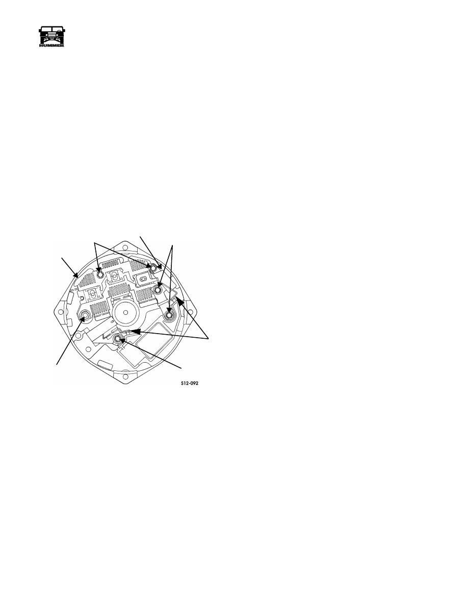
screw and two insulated screws (Figure 12-51).
Figure 12-51: Rectifier Bridge and Capacitor Strap
Location
7.
Attach stator leads to rectifier bridge and secure leads with
nuts.
8.
Install thick collar on rotor shaft (Figure 12-38).
9.
Insert rotor shaft through drive end frame and seat bearing
against thick collar.
10. Install thin collar, fan, and pulley on rotor shaft and secure
with washer and nut. Tighten nut to 40-80 lb-ft (54-109
N•m).
11. Carefully insert rotor through stator and seat ball bearing
in slip ring end frame. Be sure drive end frame and stator
are aligned and seated.
12. Install through-bolts. Tighten through-bolts evenly to
remove any slack.
13. Verify that rotor turns smoothly.
14. Remove brush retaining pin from brush holder. Be sure
brushes extend out brush holder and contact slip rings.
STUD
NUT
SCREWS
INSULATED
SCREWS
SCREW
AND WASHER
RECTIFIER
BRIDGE
CAPACITOR
STRAP
SOLDERED
CONNECTION
4-1-00

12-28
Electrical System
_______________________________________________________
®
Alternator Inoperative (No Charge)
Step
Action
Value(s)
Yes
No
1
Perform visual inspection on belt, pulleys and
battery cables. Is everything in normal operating
condition
Go to step 2.
Repair and
recheck system.
2
Using a battery load tester, place amp pickup on
the alternator fusable link wire. Start and run
vehicle at 1500 rpm, load the vehicle batteries
with 100 amps for 15 seconds. Does charging sys-
tem produce equivalent amperage.
>100 amps
Go to step 7.
go to step 3.
3
Perform battery check, refer to “battery checking
procedure” in this section. Are batteries in good
condition
Go to step 4.
Replace batter-
ies and recheck
charging sys-
tem.
4
Using a DVOM set to measure voltage, place the
negative lead on a good engine ground. Probe the
Batt. terminal on the back of the alternator. Is
voltage present?
12v
Go to step 8.
Go to step 5.
5
Using a DVOM set to measure resistance, mea-
sure resistance between the alternator case and a
negative battery connection. Is resistance below
specification.
<.2
Ω
Go to step 6.
Locate and
repair bad
ground connec-
tion.
6
Disconnect the positive battery cables, using a
DVOM set to measure resistance, measure resis-
tance between the positive battery connection and
the Batt. terminal. Is resistance below specification.?
<.2
Ω
Go to step 8.
Inspect/repair
fusible link at
alternator Batt
terminal.
7
Does voltage gauge indicate a low charge condi-
tion?
Replace gauge
and check oper-
ation.
No problem
found at this
time.
8
Using a DVOM set to measure voltage, and the
pink ignition lead disconnected from the alterna-
tor, place the negative lead on a good engine
ground and the positive lead on the pink ignition
lead. Turn the ignition key to on, is voltage
present?
12v
Go to step 9.
Locate and
repair open or
short to ground
in engine igni-
tion feed circuit.
9
Check for expanded female terminal in engine
harness connector in the alternator ignition feed
connector. Is a faulty connection found?
Replace female
terminal
Replace the
alternator
4-1-00
______________________________________________________
Electrical System 12-29
®
05745159
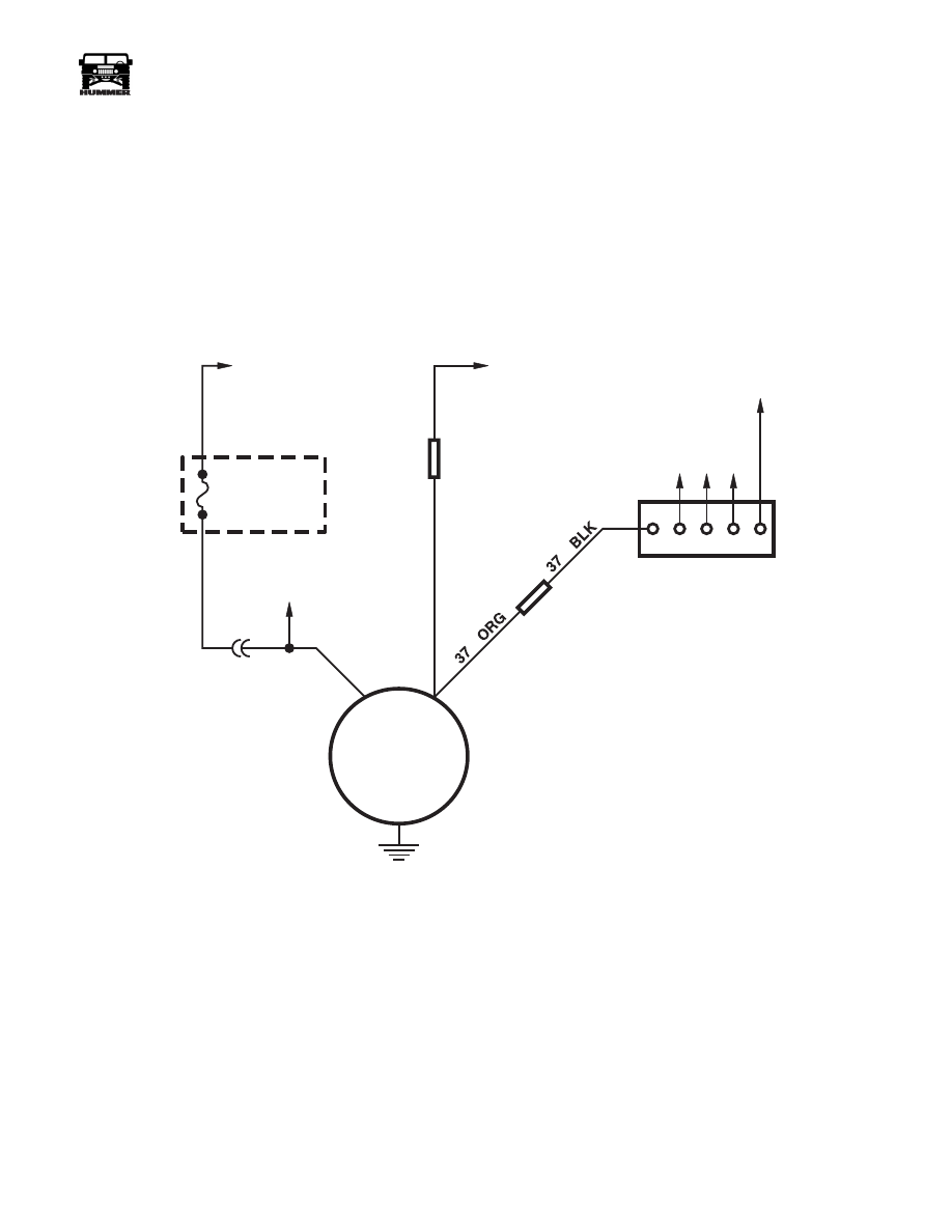
Figure 12-52: Alternator Schematic
9-S12-089
ALTERNATOR
FUSE
3B EXTERIOR
20 AMP
C4-3
PNK
EXTERIOR
POWER BUS
TO POSITIVE
BATTERY CABLE
TO EXTERIOR
FUSE BOX
TO INTERIOR
FUSE BOX
FUSIBLE
LINK
FUSIBLE
LINK
ORG
RED
TO
LOW COOLANT
SENSOR
HOT IN RUN AND START
BATTERY TERMINAL
IGN FEED
291
4-1-00
12-30
Electrical System
_______________________________________________________
®
STARTER
Removal
1.
Disconnect battery negative cable(s) and winch negative
cable, if equipped.
2.
Remove converter housing cover.
3.
Remove cap and/or adhesive sealant from starter terminal
(Figure 12-53).
4.
Disconnect starter cable or cables from starter terminals
(Figures 12-53 and 12-54).
5.
Disconnect solenoid wire from solenoid.
6.
Remove starter cable clamp.
7.
Loosen locknut and washer securing stud at front of starter
to bracket.
8.
Have helper support starter and remove starter bolts. Then
lower and remove starter and shim (if used).
Installation
1.
Position shim pack on starter.
2.
Position starter in converter housing.
3.
Slide starter stud into chassis bracket. Be sure stud nut and
washer are behind bracket.
4.
Install and tighten starter bolts to 40 lb-ft (54 N•m).
5.
Tighten stud nut to 24 lb-ft (33 N•m).
6.
Attach starter cable clamp to chassis.
7.
Connect solenoid wire to solenoid terminal with clip and
screw. Tighten screw to 22 lb-in. (2 N•m).
8.
Connect starter cable to starter terminal. Tighten nut to 25-
31 lb-ft (34-42 N•m).
9.
Cover starter terminal and solenoid terminal with silicone
sealer.
10. Install converter housing covers.
11. Connect battery negative cable.
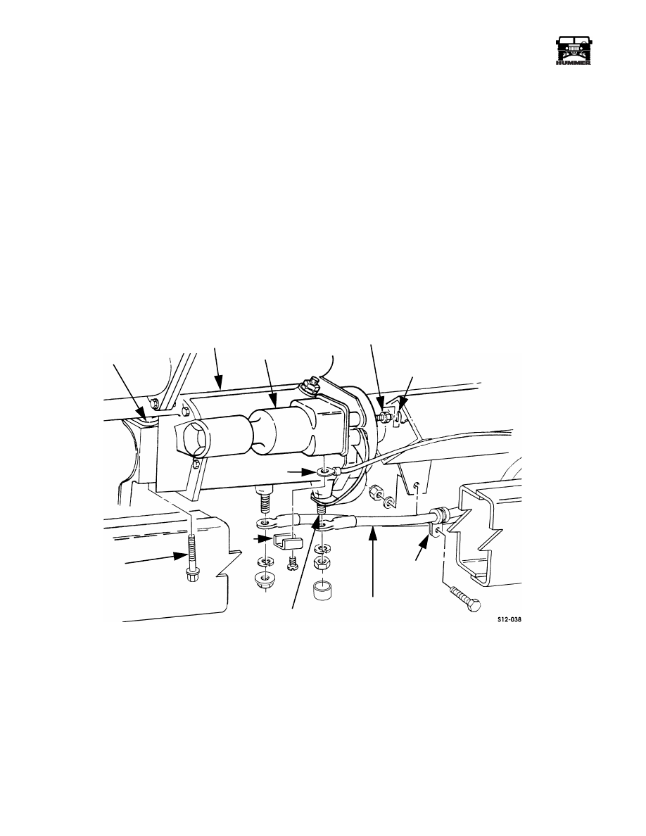
Figure 12-53: Starter Mounting
STARTER
STARTER
SOLENOID
TERMINAL
CLAMP
STARTER BOLT
CABLE
SOLENOID WIRE
CLIP
SHIM PACK
STARTER STUD
CHASSIS
BRACKET
4-1-00
Нет комментариевНе стесняйтесь поделиться с нами вашим ценным мнением.
Текст