Hummer H1 (2002+). Manual — part 199
______________________________________________________
Electrical System 12-23
®
05745159
ALTERNATOR OVERHAUL
Alternator Disassembly
1.
Remove alternator.
2.
Mark drive end frame and slip ring end frame for
assembly alignment reference.
3.
Hold rotor shaft with allen wrench and remove nut,
washer, pulley, fan, and thin collar from rotor shaft
(Figure 12-38).
4.
Remove four through-bolts from slip ring end frame and
drive end frame.
5.
Remove drive end frame and thick collar from rotor shaft.
6.
Remove three nuts from stator leads and rectifier bridge.
7.
Remove stator from slip ring end frame.
8.
Remove standard screws, insulated screws, and washer
from components in slip ring end frame.
9.
Remove nut and output stud with insulator from slip ring
end frame.
10. Remove rectifier bridge, capacitor strap, regulator
connector strap, and brush holder from slip ring end
frame.
11. Unsolder and separate brush holder and regulator
connector.
12. Unsolder and separate connector strap from regulator.
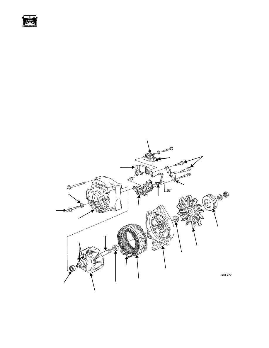
Figure 12-38: Alternator Components
OUTPUT
STUD
INSULATOR
SLIP RING
END FRAME
REGULATOR
STUD
BRUSH
HOLDER
BRUSHES
INSULATED
SCREWS
CAPACITOR
STRAP
REGULATOR
CONNECTOR STRAP
RECTIFIER
BRIDGE
BEARING
SLIP RING
ROTOR
ROTOR
SHAFT
THICK
COLLAR
STATOR
LEAD
STATOR
DRIVE END
FRAME
THIN
COLLAR
FAN
PULLEY
4-1-00
12-24
Electrical System
_______________________________________________________
®
Alternator Parts
Cleaning
Use part cleaning solvents on metal parts only. The insulating
coatings on wires in the field coil and stator can be damaged by
cleaning solvents.
Clean encapsulated and exposed wire items by wiping with a
clean cloth.
Inspection and Repair
Rotor
Inspect for cracked slip rings, damaged threads, and galling or
scoring on bearing journal surfaces on shaft (Figure 12-39).
Corrosion or light scoring on the slip rings may be removed
with 400 grit emery cloth.
Test the slip rings and field coil for opens (high resistance),
shorts (very low resistance), and grounds (low resistance) to
frame and shaft. Replace the rotor if a fault is detected.
Inspect the ball bearing for free play, roughness, leaking seals,
and other damage. Replace the bearing if necessary. Seat the
new ball bearing against the rotor shoulder.
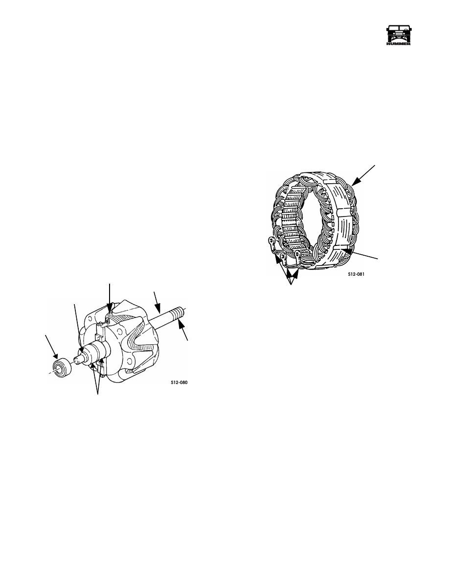
Figure 12-39: Rotor Inspection Points
Stator
Check the stator leads for continuity to ground (laminations).
Any continuity indicates a grounded stator which should be re-
placed (Figure 12-40).
Examine the stator winding for discoloration due to overheat-
ing or short to ground. Normal color is reddish brown to pur-
ple. Bare copper, dark spots, or dull black color indicates
burned spots.
Replace the stator if damaged, shorted or grounded.
Figure 12-40: Stator Inspection Points
Rectifier Bridge
Test the rectifier bridge as follows:
1.
The bridge studs are embedded in insulation. To obtain
diode readings, the ohmmeter leads must contact the cop-
per strap.
2.
Connect the ohmmeter leads to the grounded side and
strap as shown and take readings at each strap
(Figure 12-41).
3.
Repeat step 1 with test leads reversed.
4.
All three readings in steps 1 or 2 should read high
resistance in one case and low resistance in other case.
5.
Connect ohmmeter leads on positive side and strap as
shown, and take readings at each strap (Figure 12-41).
6.
Repeat process of step 4 with leads reversed.
7.
All three readings in steps 4 and 5 should be the same,
with resistance high in one set and low in the other set.
8.
If any one reading in steps 1, 2, 3, and 4 is not the same as
the other two readings, replace rectifier bridge.
BALL
BEARING
SHOULDER
SLIP RINGS
WINDINGS
SHAFT
THREADS
STATOR
LAMINATIONS
STATOR LEADS
WINDINGS
4-1-00
______________________________________________________
Electrical System 12-25
®
05745159
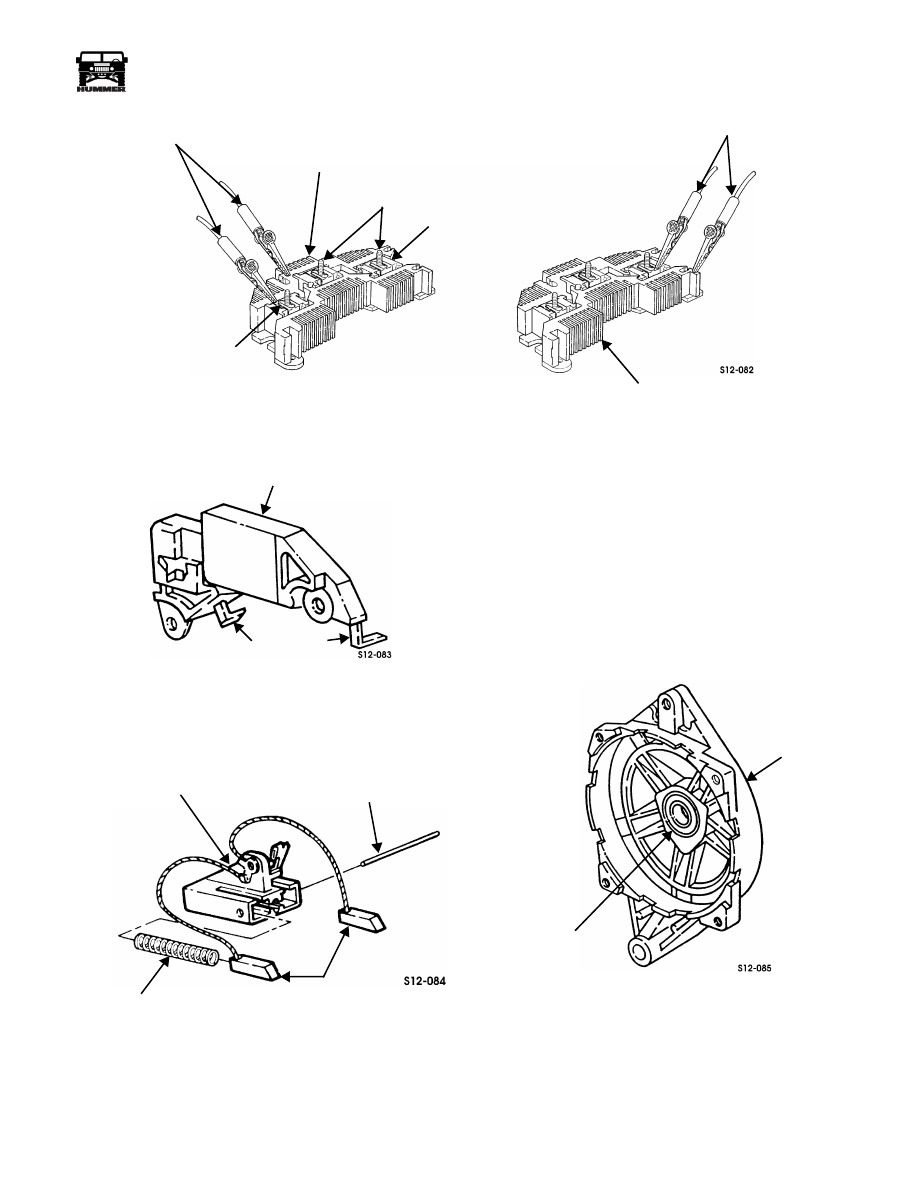
Figure 12-41: Rectifier Bridge Check
Regulator
Figure 12-42: Regulator Inspection Points
Inspect the regulator for cracks, breaks, broken contacts, or
surface defects and replace if damaged (Figure 12-42).
Brushes and Brush Holders
Figure 12-43: Brush Holder and Brushes
Check for broken or disconnected brushes, worn brushes with
length less than 0.5 in. (12.7 mm), and broken or distorted
springs. Replace brush holder and brushes as an assembly if
necessary (Figure 12-43).
NOTE: The pin that retains the brushes temporarily can be
made from locally obtained parts. A standard paper clip can be
used.
Assemble springs and brushes in the brush holder. Compress
the springs and brushes in the holder and hold them in position
with the temporary pin (pin will be removed after assembly)
(Figure 12-43).
Drive End Frame and Bearing
Inspect the bearing for roughness, looseness in bore, inner race
free play, or damaged seals. Replace the end frame and bearing
as an assembly if damaged (Figure 12-44).
Figure 12-44: Drive End Frame Inspection
Inspect the drive end frame for cracks, breaks, or damaged
threads. Replace the assembly if casting is cracked or broken.
Repair minor through-bolt and adjusting bolt thread damage
using a tap. For more serious through-bolt thread damage, re-
place the end frame.
OHMMETER LEADS
GROUNDED SIDE
STUDS
STRAP
POSITIVE SIDE
STRAP
OHMMETER LEADS
REGULATOR
CONTACTS
SPRING
BRUSH HOLDER
BRUSH
PIN
TEMPORARY
BEARING
DRIVE END
FRAME
4-1-00
12-26
Electrical System
_______________________________________________________
®
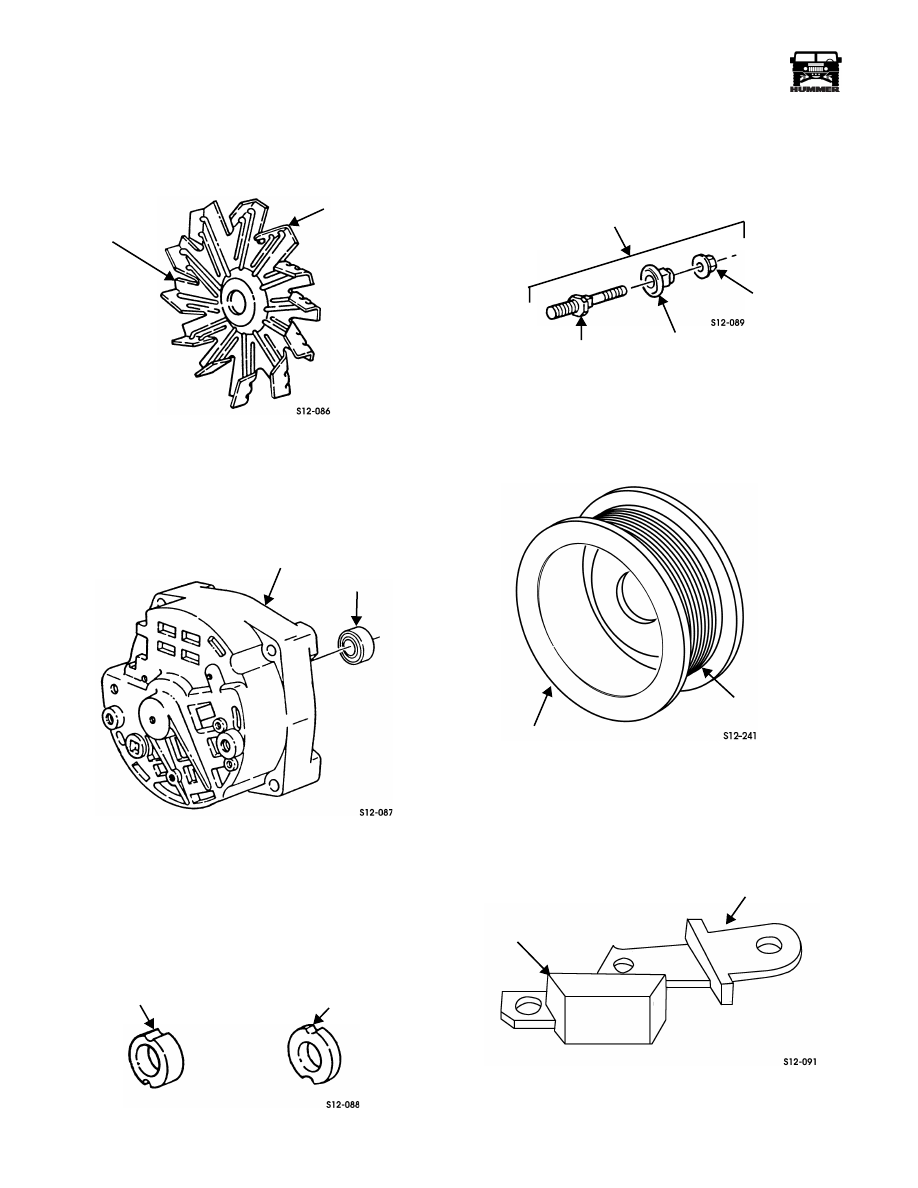
Fan
Inspect the fan for distortion, cracked blades, or broken blades.
Minor bending repair is permissible. For broken or missing
blade ends, cracks or breaks, replace the fan (Figure 12-45).
Figure 12-45: Fan Inspection Points
Slip Ring End Frame and Bearing
Inspect the bearing for roughness, looseness in retainer ring,
free play, loose inner race, or damaged seals. Replace the bear-
ing if damaged or loose (Figure 12-46).
Figure 12-46: Slip Ring End Frame
Inspect the slip ring end frame for breaks, cracks, evidence of
spun ball bearing, or damaged threads. Repair minor thread
damage. Replace the end frame if otherwise damaged.
Collars
Inspect both collars for cracks, bends, or scoring. Replace ei-
ther part if damaged (Figure 12-47).
Figure 12-47: Fan Spacers
Output Stud Assembly
Inspect the output stud assembly for cracked, or broken insula-
tor, distortion, or damaged threads. Replace the stud assembly
if any part is damaged (Figure 12-48).
Figure 12-48: Output Stud Inspection
Pulley
Inspect the pulley for distortion, breaks, or sharp edges in the
belt grooves. Remove minor burrs and sharp edges with fine
tooth file. Replace the pulley if damaged (Figure 12-49).
Figure 12-49: Alternator Pulley
Capacitor Strap
Inspect the capacitor strap for breaks, cracks, distorted case, or
surface defects. Check capacitor for continuity. Replace if
damaged (Figure 12-50).
Figure 12-50: Capacitor Strap
FAN
FAN BLADE
SLIP RING
END FRAME
BEARING
THIN COLLAR
THICK COLLAR
STUD
INSULATOR
NUT
OUTPUT STUD
ASSEMBLY
PULLEY
BELT GROOVES
STRAP
CAPACITOR
4-1-00
Нет комментариевНе стесняйтесь поделиться с нами вашим ценным мнением.
Текст