Hummer H1 (2002+). Manual — part 86
___________________________________________
Transmission/Transfer Case 5-143
®
05745159
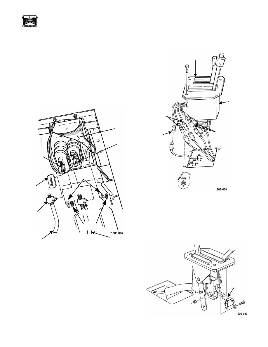
SHIFT CONTROL ASSEMBLY REMOVAL
NOTE:
Wavy washers eliminate any potential transfer case
shift linkage rattle (Figure 5-54). If a rattle is present on a vehi-
cle not equipped with a wavy washer, install one as shown. Re-
fer to parts manual for wavy washer part number.
NOTE:
Open shifter boot cover (unfasten snaps and pull apart
velcro strips) for access to shifter linkage.
1.
Remove driver side inner kick panel.
2.
Disconnect shift rod trunnions at housing shift arms
(Figure 5-54).
Figure 5-54: Shift Rod Connection (Illustration
Shown with Shifter Boot Cover Opened)
3.
Remove two shift control boot protectors.
4.
Remove shift control housing bolts and remove assembly
from body (Figure 5-55).
5.
Move shift boot away from shift control housing for
access to wires (Figure 5-55).
6.
Remove wiring tie strap.
NOTE:
Tag wires for installation reference.
7.
Disconnect body harness wires from backup light switch.
8.
Disconnect body harness wires from park/neutral position
switch wires.
Figure 5-55: Harness Wire Identification
9.
Disconnect body harness lead from shift indicator wire.
10. Disconnect interlock cable at shifter (Figure 5-56).
11. Remove boot from shift control housing.
12. Remove shift control assembly.
Figure 5-56: Interlock Cable Attachment
SHIFT
ARM
TRANSFER
CASE
SHIFT ROD
TRUNNION
TRANSMISSION
SHIFT ROD
SHIFT
ARM
BOOT
PROTECTOR
WAVY
WASHERS
TRUNNION
FLAT
WASHERS
SHIFTER
BOOT
COVER
(SHOWN OPEN)
SHIFT
CONTROL
HOUSING
SHIFT CONTROL
ASSEMBLY
SHIFT
INDICATOR
WIRES
BACKUP
LIGHT
SWITCH
WIRES
PARK/NEUTRAL
POSITION
SWITCH WIRES
SHIFT
INTERLOCK
CABLE
5-144
Transmission/Transfer Case
___________________________________________
®
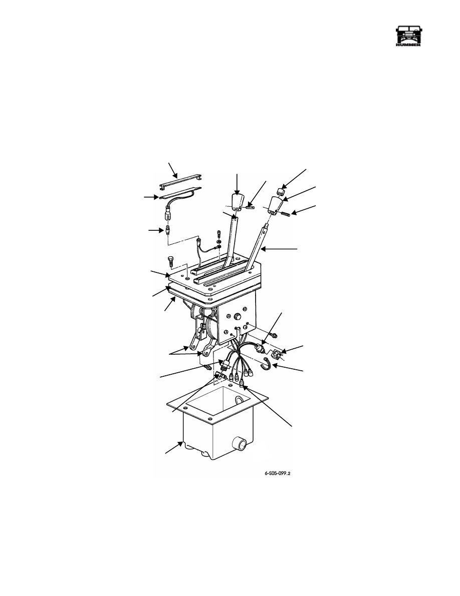
SHIFT CONTROL ASSEMBLY SERVICE
NOTE:
Shifter Boot Cover (procedure in this section) must be
removed for access to Shifter Control Boot.
The shift control housing and shift arms are not serviceable.
The shift arm mechanisms can be lubricated to correct a bind
condition when necessary. However, if any of the housing
components are worn, or damaged, the housing must be re-
placed as an assembly.
The only control assembly parts that can be replaced sepa-
rately, include the following (Figure 5-57):
• shift indicators
• shift knobs and spring pins
• housing cover plate and seal
• switches and retaining nuts
• wiring tie straps
• indicator bulb
Figure 5-57: Shift Control Assembly Serviceable Components
(Illustration Shown with Shifter Boot Cover Removed)
SHIFT
KNOB
SPRING
PIN
RELEASE
BUTTON
SHIFT
KNOB
SPRING
PIN
TRANSMISSION
LEVER
SWITCH
NUT
TIE STRAP
SHIFTER
BOOT
SWITCH
NUT
SEAL
COVER PLATE
INDICATOR
BULB
SWITCH AND
LAMP HARNESS
HOUSING
SHIFT
ARMS
BACKUP
LAMP SWITCH
SHIFT
CONTROL
HOUSING
TRANSFER
CASE LEVER
PARK/NEUTRAL
POSITION
SWITCH
TRANSMISSION
SHIFT INDICATOR
TRANSFER CASE
SHIFT INDICATOR
COVER
___________________________________________
Transmission/Transfer Case 5-145
®
05745159
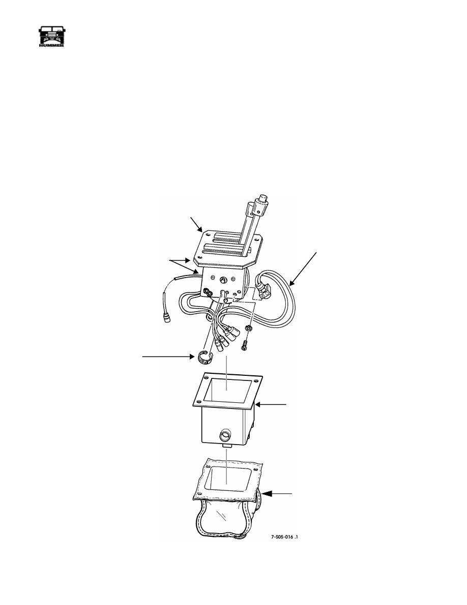
PARK/NEUTRAL POSITION OR BACKUP LAMP
SWITCH REPLACEMENT
1.
Remove driver side inner kick panel.
2.
Open shifter boot cover for access to shift control arms.
3.
Disconnect shift rods at shift control arms.
4.
Remove bolts attaching shift control housing to tunnel
floor.
5.
Lift up for access and remove interlock cable.
6.
Remove shift control assembly.
7.
Remove shifter boot cover and shifter boot (Figure 5-58).
8.
Remove position switch screws and remove switch from
housing.
9.
Remove tie strap and disconnect switch leads.
10. Disconnect backup or position switch wires at body
harness.
11. Install switch on shift control housing and secure with
lockwashers and screws.
12. Position wires in shifter boot and install shifter boot on
housing assembly.
13. Install shift control assembly.
14. Install housing attaching screws.
15. Connect shift rods to control assembly shift arms.
16. Install inner kick panel.
Figure 5-58: Shift Housing Switch Replacement
SHIFT CONTROL
ASSEMBLY
CONTROL
HOUSING
TIE STRAP
PARK/NEUTRAL
POSITION SWITCH
SHIFTER
BOOT
SHIFTER BOOT
COVER
5-146
Transmission/Transfer Case
___________________________________________
®
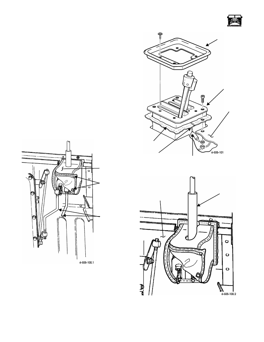
SHIFTER BOOT COVER REPLACEMENT
A “shifter boot cover” protects the shifter boot and linkage.
The shifter boot cover is made of a silicone coated fiberglass,
heat resistant material. This material provides the additional
benefits of reduced noise and heat intrusion from under the ve-
hicle into the passenger compartment.
Removal
WARNING: Exhaust system components can be ex-
tremely hot. To avoid injury, do not touch hot exhaust
system components.
1.
The exhaust system passes directly under the shift control
assembly. Loosen, but do not remove, the two clamps
holding the heat shield to the exhaust pipe so that it can be
moved out of the way as necessary when performing the
following procedure.
2.
Unfasten shifter boot cover snaps and pull apart velcro
strips to open cover (Figure 5-59).
Figure 5-59: Shift Rod Removal
3.
Remove shift rods from shift control assembly.
4.
Remove bezel from shift control assembly (Figure 5-60).
5.
Remove fasteners securing shift control assembly to tunnel
and raise shift control assembly until interlock cable
contacts tunnel, restricting further upward movement.
6.
Cut shifter boot cover from the lip to the interlock cable
hole as shown (Figure 5-60).
7.
Work shifter boot cover lip out of tunnel opening and
remove from under vehicle (Figure 5-61).
Figure 5-60: Cutting Shifter Boot Cover
Figure 5-61: Shifter Boot Cover Removal
SHIFTER
SNAPS
SHIFT
BOOT
COVER
RODS
BEZEL
SHIFT CONTROL
TUNNEL
SHIFTER BOOT
CUT FROM COVER LIP TO
INTERLOCK CABLE
INTERLOCK
ASSEMBLY
COVER LIP
CABLE
TUNNEL
INTERLOCK
(UNDERNEATH VEHICLE)
CABLE
Нет комментариевНе стесняйтесь поделиться с нами вашим ценным мнением.
Текст