Jaguar XJ (X350). Manual — part 251

-> No
INSTALL a new brake switch. CLEAR the DTC, test the system for normal operation.
G531322t4 : CHECK THE OPERATION OF THE BRAKE SWITCH (PEDAL
PRESSED)
1. Press the brake pedal. 2. Measure the resistance between:
Brake switch connector CR078, component side Brake switch connector CR078, component side
Pin 01
Pin 02
•
Is the resistance greater than 10 ohms?
-> Yes
INSTALL a new brake switch. CLEAR the DTC, test the system for normal operation.
-> No
GO to Pinpoint Test
G531322t5
.
G531322t5 : CHECK THE POWER SUPPLY TO THE BRAKE PEDAL SWITCH
1. Key on, engine off. 2. Measure the voltage between:
Brake switch connector CR078, harness side
Battery
Pin 01
Negative terminal
•
Is the voltage less than 10 volts?
-> Yes
REPAIR the circuit between the brake switch and battery. This circuit includes fuse 35 of the primary
junction box. For additional information, refer to the wiring diagrams. CLEAR the DTC, test the
system for normal operation.
-> No
GO to Pinpoint Test
G531322t6
.

G531322t6 : CHECK THE BRAKE SWITCH SIGNAL CIRCUIT FOR SHORT
CIRCUIT TO GROUND
1. Key off. 2. Measure the resistance between:
Brake switch connector CR078, harness side
Battery
Pin 02
Negative terminal
•
Is the resistance less than 100 Kohms?
-> Yes
REPAIR the short circuit. For additional information, refer to the wiring diagrams. CLEAR the DTC, test
the system for normal operation.
-> No
GO to Pinpoint Test
G531322t7
.
G531322t7 : CHECK THE BRAKE SWITCH SIGNAL CIRCUIT FOR SHORT
CIRCUIT TO POWER
1. Measure the resistance between:
Brake switch connector CR078, harness side
Battery
Pin 02
Positive terminal
•
Is the resistance less than 100 Kohms?
-> Yes
REPAIR the short circuit. For additional information, refer to the wiring diagrams. CLEAR the DTC, test
the system for normal operation.
-> No
GO to Pinpoint Test
G531322t8
.
G531322t8 : CHECK THE BRAKE SWITCH SIGNAL CIRCUIT FOR HIGH
RESISTANCE
1. Disconnect the ECM electrical connector, EC300. 2. Measure the resistance between:
Brake switch connector CR078, harness side ECM connector EC300, harness side
www.
Pin 02
Pin 41
•
Is the resistance less than 10 ohms?
-> Yes
CHECK for CAN DTCs indicating a network fault.
-> No
REPAIR the high resistance circuit. For additional information, refer to the wiring diagrams. CLEAR the
DTC. TEST the system for normal operation.
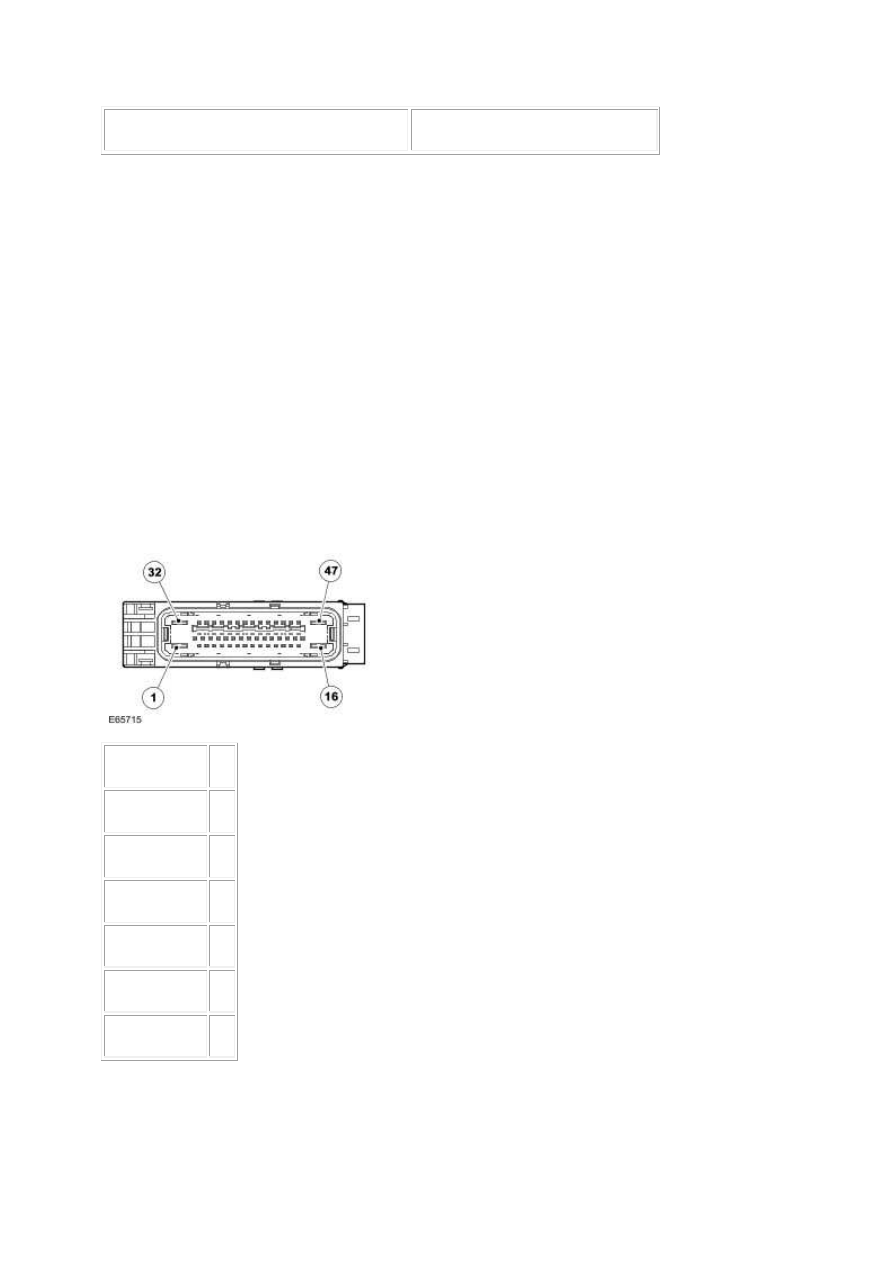
PINPOINT TEST G531322p3 : MODULE
SUPPLIES AND GROUNDS
G531322t9 : CHECK THE MODULE PUMP SUPPLY
1.
Circuit
Pin
Pump supply
01
Valves supply
32
Batt supply
02
Ignition supply 08
Pump ground
47
Valve ground
16
2. Key off. 3. Disconnect the ABS module connector, EC030. 4. Measure the voltage between:

EC030, harness side
Battery
Pump supply, pin 01 Negative terminal
•
Is the voltage between 9 and 15 volts?
-> Yes
GO to Pinpoint Test
G531322t10
.
-> No
REPAIR the supply circuit as necessary. This circuit includes fuse 20 of the front power distribution
box. For additional information, refer to the wiring diagrams. Clear the DTC, test the system for
normal operation.
G531322t10 : CHECK THE MODULE VALVES SUPPLY
1. Measure the voltage between:
EC030, harness side
Battery
Valves supply, pin 32 Negative terminal
•
Is the voltage between 9 and 15 volts?
-> Yes
GO to Pinpoint Test
G531322t11
.
-> No
REPAIR the supply circuit as necessary. This circuit includes fuse 04 of the front power distribution
box. For additional information, refer to the wiring diagrams. Clear the DTC, test the system for
normal operation.
G531322t11 : CHECK THE MODULE BATT SUPPLY
1. Measure the voltage between:
EC030, harness side
Battery
Batt supply, pin 02
Negative terminal
www.
Нет комментариевНе стесняйтесь поделиться с нами вашим ценным мнением.
Текст