Jaguar XJ (X350). Manual — part 517

3
—
Spiral joint oil control
4
—
Ring gap lower compression
5
Upper compression ring
6
Lower compression ring
7
Oil control ring
All pistons are common single grade/single part number for all engines.
The piston top ring is a taper type and is fitted with a taper to the top of the piston. All rings marked
'top' are assembled with top to uppermost. All rings must be spaced evenly around the piston before
installing. The circumference gap of the double bevelled oil control ring must be opposite to the
spiral control joint.
Piston bowl volume is 20.025cc and the compression ratio is 17.3:1.
Cylinder Heads and Valve Gear
The cylinder head is of high quality aluminium and cannot be reworked. The cylinder head is secured
to the engine block by eight bolts.
The cylinder head incorporates four valves per cylinder, glow plugs and a knock sensor. A vertically
centrally placed fuel injector guarantees maximum distribution of fuel into the combustion chamber.
The cylinder head gasket is a three layer laminated steel construction that has an excellent service
life and sealing properties. The cylinder head gasket is available in five different thicknesses
depending on the piston protrusion height. The cylinder head gaskets are identified by serrations cut
into the front end of the gasket.
The valves are operated directly by steel roller rockers with hydraulic lash adjusters.
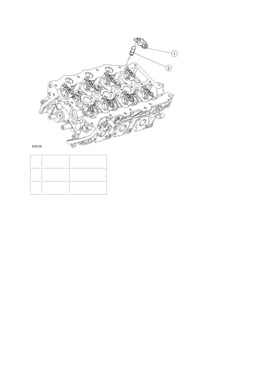
Item
Part Number
Description
1
—
Steel rocker
2
—
Hydraulic adjuster
Inlet Manifold
The induction is designed to optimise torque across the engine speed/load range. The air charge
enters the induction manifold from the EGR throttle valve and passes into the plenum for
distribution to the cylinders.
The purpose of the plenum is to maximise the air charge into the cylinders.
The inlet manifolds are of plastic composite construction and are handed for the left and right hand
bank. The manifolds incorporate a twin plenum intake system and integrated cam covers. The
plenum systems are vacuum operated, these are located at the rear of the manifolds and are ECM
controlled
The inlet manifolds/cam covers are secured to the cylinder head by 13 shouldered bolts and sealed
by means of rubber gasket.
Camshafts
The camshaft's construction is of hollow steel tube with pressed on syntered lobes. There are two
camshafts per cylinder head. The camshafts have pressed on drive sprockets which are marked for
timing purposes. The interconnecting drive chain is also marked for valve timing. The drive chain has
www.
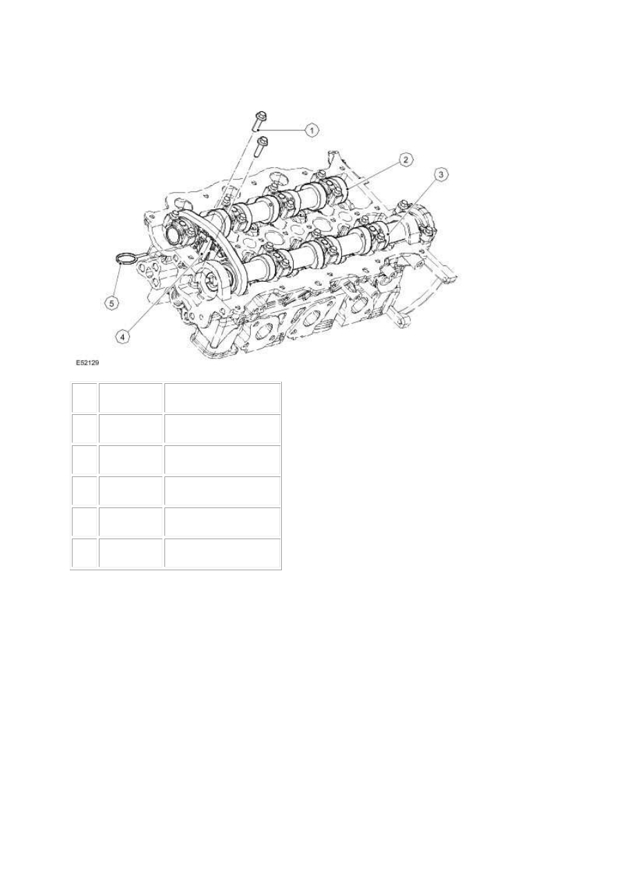
a hydraulic tensioner. Both banks are of similar construction. They are not interchangeable.
Item
Part Number
Description
1
—
Tensioner securing bolts
2
—
Camshaft bearing caps
3
—
Camshaft
4
—
Chain tensioner
5
—
Tensioner retaining pin
The drive sprockets also form the thrust faces for the camshaft. In production camshaft endfloat is
set to 0.065mm-0.185mm.
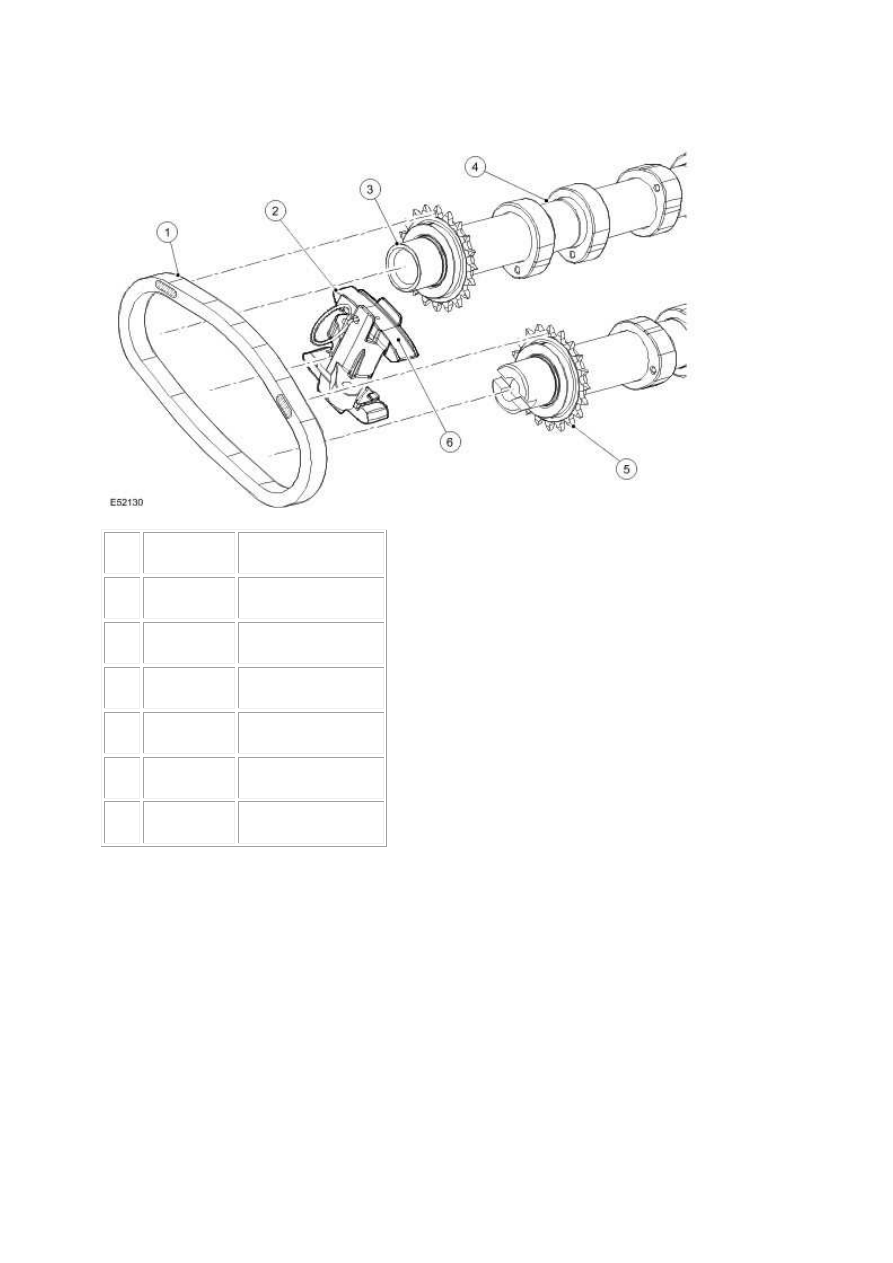
Item
Part Number
Description
1
—
Drive chain
2
—
Tensioner locking pin
3
—
Camshaft
4
—
Cam lobe
5
—
Drive gear
6
—
Tensioner
Camshaft Bearings
The camshafts are supported in five line bored bearings. The bearing caps, which are individually
identified, must be fitted in the correct sequence.
www.
Нет комментариевНе стесняйтесь поделиться с нами вашим ценным мнением.
Текст