Jaguar XJ (X350). Manual — part 1309
Connector access
Connector
number
Function
Location
VL01
Screen connector
At left-hand screen,
Video Display
VR01
Screen connector
At right-hand screen,
Video Display
VL02
Intermediate connector
In the front seat back, <<501-10>>
VR02
Intermediate connector
In the front seat back, <<501-10>>
TL91
Intermediate connector
Beneath the right-hand front seat (move the seat fully
forward and to the fully raised position).
TL92
Intermediate connector
Beneath the left-hand front seat (move the seat fully
forward and to the fully raised position).
TL85, TL86,
TL87, TL20
Audio video selector
module connectors
Behind the rear seat back,
Video System Module
RC04
Intermediate connector
Behind the rear seat back, below the audio video
selector module,
Video System Module
RC01, RC03
Control panel connectors
In the rear armrest,
Rear Passenger Entertainment Control Panel
Pinpoint Tests
CAUTION: Electronic modules are sensitive to static electrical charges. If exposed to these
charges, damage may result.
CAUTION: When probing connectors to take measurements in the course of the pinpoint
tests, use the adaptor kit, part number 3548-1358-00.
CAUTION: The small size of the pins in the audio/visual harnesses mean that probing must
be done with great care. The use of suitable adaptors is very important, and an assistant to hold
the harness would make probing far easier.
NOTE:
Repairs to the harnesses would not be viable. If a circuit fails a pinpoint test, the harness should
be replaced.
NOTE:
When performing electrical voltage or resistance tests, always use a digital multimeter (DMM)
accurate to 3 decimal places, and with an up-to-date calibration certificate. When testing
resistance, always take the resistance of the DMM leads into account.
www.
NOTE:
Check and rectify basic faults before beginning diagnostic routines involving pinpoint tests.
PINPOINT TEST G240121p1 : CHECK
THE NTSC SIGNAL AT THE REAR
SCREENS
G240121t1 : CHECK THE SCREENS AND CIRCUITS USING THE VIDEO/AUDIO
TESTER (NTSC)
1. Turn the ignition switch to the ACC position. 2. Set the rear entertainment control panel to AUX1
for both screens (refer to Selecting AUX1; AUX2 and audio functions in this section). 3. Set the rear
screens to AUTO (refer to Selecting AUTO/PAL/NTSC in this section). 4. Connect the video/audio
tester to AUX1, video (yellow). 5. Select NTSC on the video/audio tester, make sure the blue LED is
illuminated.
•
Is the NTSC test image displayed on both screens?
-> Yes
For PAL signal tests, GO to Pinpoint Test G240121p4.
.
-> No
If the test image is displayed on the left-hand screen only, GO to Pinpoint Test G240121p2.
.
If the test image is displayed on the right-hand screen only, GO to Pinpoint Test G240121p3.
.
If the test image is displayed on neither screen, GO to Pinpoint Test G240121p4.
.
PINPOINT TEST G240121p2 : CHECK
THE PAL SIGNAL AT THE THE RIGHT-
HAND SCREEN
G240121t2 : CHECK THE PAL SIGNAL AT THE RIGHT-HAND SCREEN
1. Turn the ignition switch to the ACC position. 2. Set the rear entertainment control panel to AUX1
for both screens (refer to Selecting AUX1; AUX2 and Audio functions in this section). 3. Set the rear
screens to AUTO (refer to Selecting AUTO/PAL/NTSC in this section). 4. Connect the video/audio
tester to AUX1, video (yellow). 5. Select PAL on the video/audio tester, make sure the blue LED is
illuminated. 6. Observe the rear screen image.
•
Is the PAL test image displayed on the right-hand screen?
-> Yes
INSTALL a new right-hand screen,
Rear Passenger Entertainment Control Panel (The screen cannot decode a NTSC signal).
-> No
GO to Pinpoint Test G240121t3.
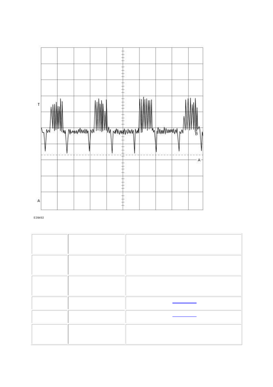
G240121t3 : CHECK THE SIGNAL TO THE RIGHT-HAND REAR SCREEN
INTERMEDIATE CONNECTOR TL91
1. Reposition the right-hand front seat fully forward and to the fully raised position. 2. Turn the
ignition switch to the OFF position. 3. Make sure the video/audio tester is switched OFF. 4.
Disconnect the intermediate connector, TL91. 5. Connect the oscilloscope. Refer to Oscilloscope set-
up procedure in this section. 6. Turn the video/audio tester ON, and to the TEST position by holding
in the TEST button while selecting PAL or NTSC. The blue and red LEDs will illuminate. 7. Turn the
ignition switch to the ON position. 8. Using suitable adaptors, and an assistant if necessary, connect
the red oscilloscope probe to TL91, pin 15 (RW). 9. Using suitable adaptors, and an assistant if
necessary, connect the black oscilloscope probe to TL91, pin 09 (B).
•
Is the waveform similar to the example in Waveforms in this section?
-> Yes
GO to Pinpoint Test G240121t5.
-> No
GO to Pinpoint Test G240121t4.
G240121t4 : CHECK THE CIRCUIT FROM THE AUDIO VIDEO SELECTOR
MODULE TO THE INTERMEDIATE CONNECTOR TL91 FOR CONTINUITY
1. Turn the ignition switch to the OFF position. 2. Make sure the video/audio tester is switched OFF.
3. Disconnect the audio video module electrical connector, TL87. 4. Using suitable adaptors, measure
the resistance between TL91, pin 15 (RW) and TL87, pin 15 (RW). 5. Using suitable adaptors, measure
the resistance between TL91, pin 09 (B) and TL87, pin 09 (B).
www.
Нет комментариевНе стесняйтесь поделиться с нами вашим ценным мнением.
Текст