Jaguar XJ (X350). Manual — part 620
Description and operation
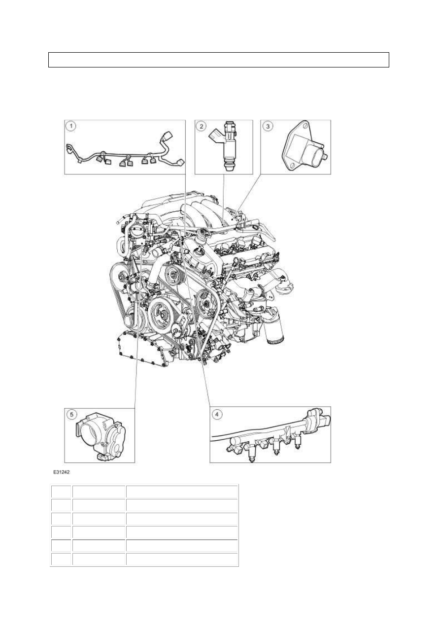
Fuel Charging and Controls
Item Part Number
Description
1
—
Fuel charging wiring harness
2
—
Fuel injector
3
—
Fuel pressure sensor
4
—
Fuel injection supply manifold
5
—
Throttle body
The electronic returnless fuel system has the advantages of reduced fuel temperature and fuel
tank vapor caused by constant fuel recirculation. The system delivers the correct amount of
fuel to the engine under all conditions and at a constant pressure differential with respect to
manifold absolute pressure.
Fuel is supplied at high pressure to the fuel injectors via a fuel injection supply manifold
which incorporates fuel injectors, a fuel pressure sensor and a fuel temperature sensor. The
engine control module (ECM) increases the fuel pressure to minimize fuel vapor formation to
maintain fuel flow across the injectors.
The throttle body assembly is calibrated during assembly, no adjustments are required or
permitted. The throttle motor is a 12 volt DC motor which, via movement of the throttle
blade, controls the amount of air flowing into the engine.
www.

Diagnosis and testing
Fuel Charging and Controls - VIN Range:
G00442->G45703
Inspection and Verification
1 . Verify the customer concern.
2 . Confirm which, if any, warning lights and/or messages were displayed on the instrument cluster.
NOTE:
If any warning lights and/or messages were displayed when the fault occurred, refer to the
Driver Information table for DTCs associated with the display, then to the DTC index table for
possible sources and actions. Some warnings will appear to clear when the ignition is cycled. This
is often because the warning has flagged as a result of one of the vehicle's on-board diagnostic
routines having run to detect the fault. If the same routine is not run when the ignition is
switched ON, the warning will not reflag until the routine does run. See the DTC summaries for
drive cycle routines.
3 . Visually inspect for obvious signs of mechanical or electrical damage.
Visual Inspection Chart
Mechanical
Electrical
•
Engine oil level
•
Cooling system coolant level
•
Fuel level
•
Fuel contamination/grade/quality
•
Throttle body
•
Poly-vee belt
•
Fuses
•
Wiring harness
•
Electrical connector(s)
•
Sensor(s)
•
Engine control module (ECM)
•
Transmission control module
1 . Verify the following systems are working correctly:
•
Air intake system
•
Cooling system
•
Charging system
•
Ignition system
2 . If an obvious cause for an observed or reported concern is found, correct the cause (if possible)
before proceeding to the next step.
3 . Where the Jaguar approved diagnostic system is available, complete the S93 report before
clearing any or all fault codes from the vehicle.
NOTE:
If a DTC cannot be cleared, then there is a permanent fault present that flags again as soon as it
is cleared. (The exception to this is P1260, which will only clear following an ignition OFF/ON
cycle after rectification).
4 . If the cause is not visually evident and the Jaguar approved diagnostic system is not available, use
a fault code reader to retrieve the fault codes before proceeding to the Diagnostic Trouble Code
(DTC) Index Chart, or the Symptom Chart if no DTCs are set.
5 . Using the Jaguar approved diagnostic system where available, and a scan tool where not, check
the freeze frame data for information on the conditions applicable when the fault was flagged. The
format of this will vary, depending on the tool used, but can provide information useful to the
technician in diagnosing the fault.
CAUTION: When probing connectors to take measurements in the course of the pinpoint
tests, use the adaptor kit, part number 3548-1358-00.
NOTE:
When performing electrical voltage or resistance tests, always use a digital multimeter (DMM)
accurate to 3 decimal places, and with an up-to-date calibration certificate. When testing
resistance, always take the resistance of the DMM leads into account.
NOTE:
Check and rectify basic faults before beginning diagnostic routines involving pinpoint tests.
Symptom
Possible source
Action
Engine cranks, but does
not fire
•
Engine breather system
disconnected/restricte
d
•
Ignition system
•
Fuel system
•
Harness
•
CKP sensor
•
ECM fault
Check engine breather system, <<303-08>>
For ignition system, <<303-07>> Check fuel
pressure, <<310-01>> For CKP tests, <<303-
14>> Contact dealer technical support for
advice on possible ECM failure.
www.
Нет комментариевНе стесняйтесь поделиться с нами вашим ценным мнением.
Текст