Jaguar XJ (X350). Manual — part 1024

G549822t273 : CHECK THE INERTIA SWITCH TO ECM CIRCUIT FOR SHORT
CIRCUIT TO POWER
1. Measure the resistance between:
CR02, harness side
Battery
Pin 03
Positive terminal
Is the resistance greater than 100 Kohms?
-> Yes
GO to Pinpoint Test G549822t280.
-> No
REPAIR the short circuit. For additional information, refer to the wiring diagrams. Clear any DTCs, test
the system for normal operation.
G549822t280 : CHECK THE INERTIA SWITCH TO ECM CIRCUIT FOR HIGH
RESISTANCE
1. Disconnect electrical connector, PI41. 2. Measure the resistance between:
CR02, harness side PI41
Pin 03
Pin 15
Is the resistance less than 10 ohms?
-> Yes
An intermittent fault may be present in the wiring harness. Visually check for chaffed wires or other
physical damage to the harness. If no fault is found in the circuit, suspect the following
component(s): -Inertia switch connector -Inertia switch - ECM connector - ECM
-> No
REPAIR the high resistance circuit. For additional information, refer to the wiring diagrams. Clear any
DTCs, test the system for normal operation.
Removal and installation
Brake Pedal Position (BPP) Switch
Removal
1 . Switch the ignition on.
2 . Position the front seat fully rearwards.
3 . Switch the ignition off.
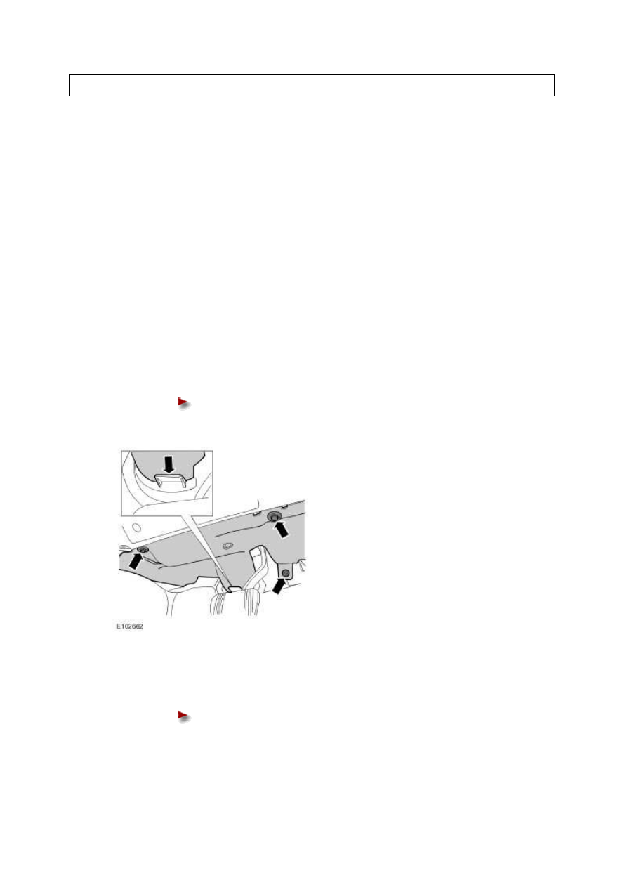
4 . Remove the driver's side footwell trim panel.
Release the 3 clips.
5 . Release the brake pedal position (BPP) switch.
Rotate the BPP switch 45 degrees counter-clockwise.
www.
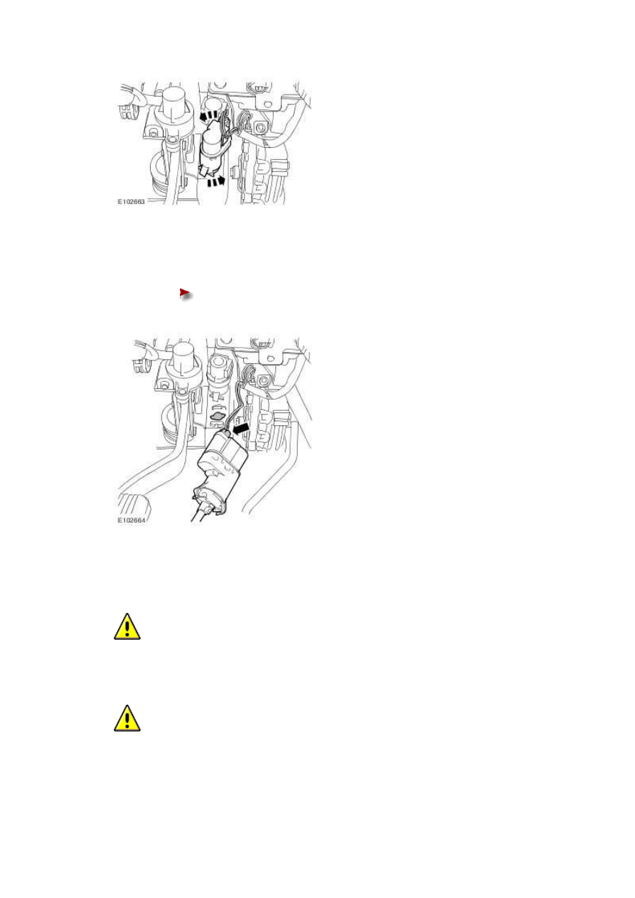
6 . Remove the BPP switch.
Disconnect the electrical connector.
Installation
1
.
CAUTION: Make sure that the brake pedal remains in the rest position during this
procedure.
CAUTION: The bracket is keyed to avoid incorrect orientation. Failure to correctly
align the switch may result in damage to the vehicle.

CAUTION: Make sure that the pedal box, booster-to-brake pedal assembly and
switch bracket are all installed correctly before installing the switch.
Install the BPP switch.
Locate the BPP switch in the bracket.
Rotate the BPP switch 45 degrees clockwise.
2 . Connect the electrical connector.
3 . Install the driver's side footwell trim panel.
Align the trim panel with the guide.
Install the 3 clips.
www.
Нет комментариевНе стесняйтесь поделиться с нами вашим ценным мнением.
Текст