Engines Iveco C87 / Cursor 87. Manual — part 12
114269
114270
Figure 44
Figure 45
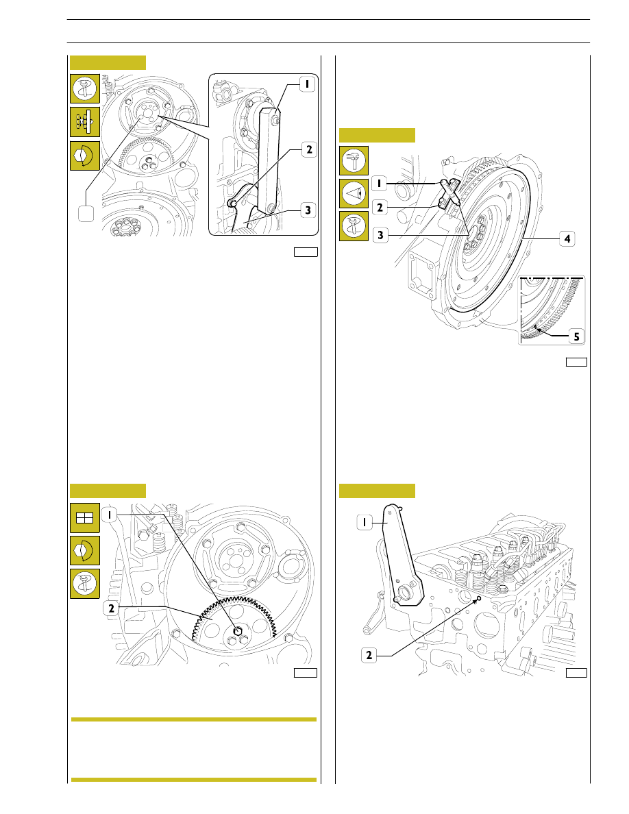
Apply gage 99395222 (1), check and adjust position of
connecting rod (3) for relay gear, lock screw (2) at required
torque.
Refit relay gear (2) and lock screws (1) using six-splined
spanner at required torque.
The relay gear (1) bushing can be replaced when
worn out. After securing bushing, grind it to reach
dia. 58.010
± 0.10 mm.
NOTE
Rotate the crankshaft with the tool 99360341 (3, Figure 53)
so that the opening marked with two references (5) is visible
from the lower inspection window in the flywheel cover
casing.
In this condition, insert the tool 99360612 (1) via the housing
(2) for the engine rpm sensor in the opening (3) in the engine
flywheel (4).
115064
TIMING
CAMSHAFT
AND
FLYWHEEL
USING TOOL 99395223
Timing camshaft
Figure 46
116052
Figure 47
Fit the tool 99395223 (1) at the front of the camshaft.
4
SECTION 3 - INDUSTRIAL APPLICATION
17
F2C CURSOR ENGINES
116053
117691
116055
114025
Figure 48
Figure 49
Figure 50
Figure 51
Rotate the tool (1) 99395223 in order to insert the pin (3) in
the opening (2, Figure 47) in the head. Fasten the tool (1)
99395223 using two M8x1.25 bolts (2).
Fit the camshaft drive gear (1) so that the fastening openings
in the shaft are aligned with the slots (2) in the drive gear.
Position the gear (1) taking care to position the spokes (4) as
illustrated. This operation is necessary in order to be able to
fit the flywheel correctly which can only be fitted in one
position in relation to the gear.
Tighten the fixing bolts (3).
Install crosspieces (1) on valve rod.
Apply tool 99360558 (1) to rocker arm shaft (2) and install
shaft on cylinder head.
Lock retaining screws at required torque.
Before refitting rocker arm shaft assembly, check
that all adjustment screws have been fully unlocked.
NOTE
18
SECTION 3 - INDUSTRIAL APPLICATION
F2C CURSOR ENGINES
Base - June 2006
114284
Figure 52
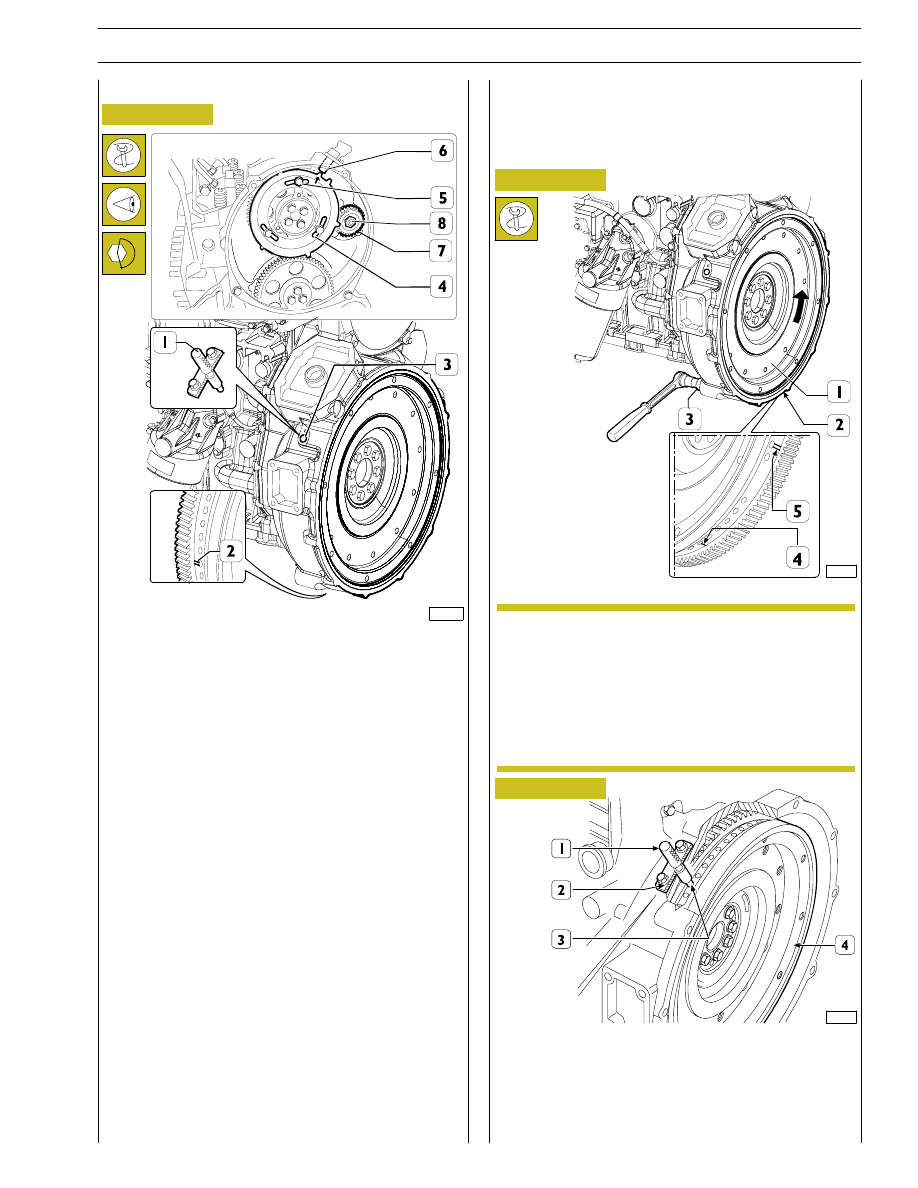
Fit the high pressure pump gear (7)tightening the nut (8) to
torque.
Use the flat washer (PN 17095914) in conjunction with the
nut replacing the one supplied with the Bosch CP3 pump.
Fit the flywheel (4) so that the toothe marked with the arrow
(
→) is in line with the sensor housing (6).
To check that the position is correct, insert tool 99360613 in
the timing sensor (6) housing.
Proceed with tightening the bolts (5).
Remove the tools 99395223, 99360612 and 99360613.
Secure special tool 99360341 (3) to gear casing.
114279
The arrow indicated engine rotation direction.
Use tool above to rotate engine flywheel (1) in
engine rotation direction to bring cylinder 1 piston
approx. to TDC in blast phase.
This condition is reached when hole with notch (4),
following hole with two notches (5) drilled on
engine flywheel (1), is visible through manhole (2).
TIMING
CAMSHAFT
AND
FLYWHEEL
WITHOUT TOOL 99395223
Timing camshaft
71774
Figure 53
The exact position of piston no.1 at TDC is obtained when,
in conditions described above, tool 99360612 (1), through
engine rpm sensor housing (2), inserts in hole (3) drilled on
engine flywheel (4).
Otherwise, rotate engine flywheel (4) to adjust its orientation.
NOTE
Timing flywheel
Figure 54
SECTION 3 - INDUSTRIAL APPLICATION
19
F2C CURSOR ENGINES
115063
Figure 55
Figure 56
Figure 57
Rotate the camshaft so that the openings at the rear of the
engine are arranged in the configuration illustrated in the
diagram.
Install gear (1) controlling camshaft so that fastening holes on
shaft coincide with slots (2) on control gear.
114276
Figure 58
Install crosspieces (1) on valve rod.
Before refitting rocker arm shaft assembly, check
that all adjustment screws have been fully unlocked.
NOTE
Lock retaining screws (3).
Position the gear (1) taking care to position the
spokes (4) as illustrated.
This operation is necessary in order to be able to fit
the flywheel correctly which can only be fitted in one
position in relation to the gear.
NOTE
114025
Apply tool 99360558 (1) to rocker arm shaft (2) and install
shaft on cylinder head.
Lock retaining screws at required torque.
Remove tool 99360612 (1, Figure 54).
117691
Figure 59
Apply tool 99360558 (1) to rocker arm shaft (2) and install
shaft on cylinder head.
Lock retaining screws at required torque.
Remove tool 99360612 (1, Figure 54).
117693
20
SECTION 3 - INDUSTRIAL APPLICATION
F2C CURSOR ENGINES
Base - June 2006
Нет комментариевНе стесняйтесь поделиться с нами вашим ценным мнением.
Текст