Engines Iveco C87 / Cursor 87. Manual — part 10
114018
114014
114019
114020
114009
Figure 10
Figure 11
Figure 12
Figure 13
Figure 14
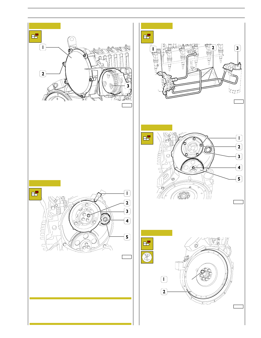
Unlock screws (1) and remove cover (2). Remove centrifugal
filter (3) below.
Use specific spanner to unlock screws (2) and remove gear (3)
complete with tune wheel.
Unlock nut (4) and remove control gear (5) of high pressure
pump.
Remove rpm sensor (1).
Disconnect fuel lines (2), unlock retaining screws and remove
high pressure pump (1). Remove fuel filter support (3)
complete with pipeline.
Unlock screws (1) and remove thrust plate (2).
Use specific spanner to unlock screws (4) and remove relay
gear (5).
Remove high pressure pump mount flange (3).
Use specific tool lock engine flywheel (2) rotation, unlock
retaining screws (1) and remove engine flywheel.
In case removal of gear (5) is difficult, release high
pressure pump screws with light beater strokes on
control shaft and remove gear (5).
NOTE
SECTION 3 - INDUSTRIAL APPLICATION
9
F2C CURSOR ENGINES

45257
Figure 15
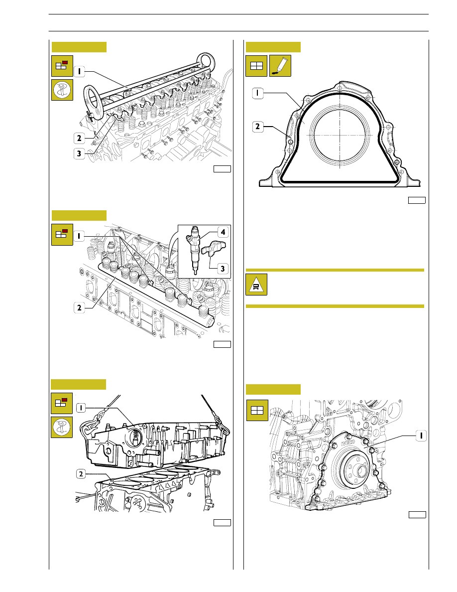
Apply extractor 99340054 (2) and remove seal (1).
114029
Figure 16
Unlock screws (1) and remove engine oil sump (3) complete
with spacer (2) and seal.
114031b
Figure 17
Unlock screws and remove suction rose (1).
114022
Figure 18
Unlock screws (1) and remove flywheel box (2).
114023
114024
Figure 19
Figure 20
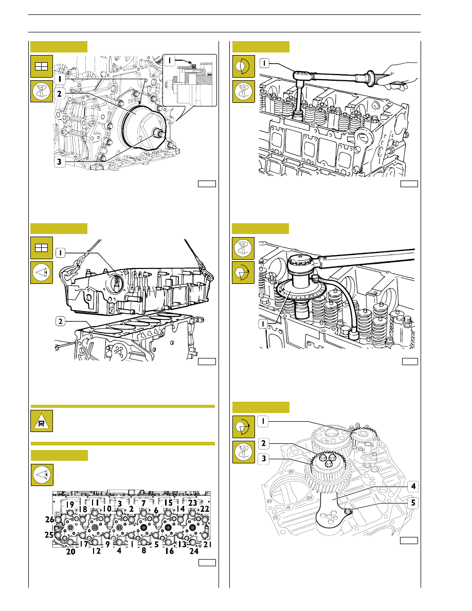
Remove screws (2) and double gear (3).
Remove retaining screw (5) and connecting rod (4).
Remove oil pump (1).
- Unlock rocker arm shaft retaining screws (4).
- Disconnect fuel pipelines (1) from injector rail, fuel supply
line (2) of high pressure pump to rail and return line (3).
10
SECTION 3 - INDUSTRIAL APPLICATION
F2C CURSOR ENGINES
Base - June 2006
114025
114027
Figure 21
Figure 22
Apply tool 99360558 (1) to rocker arm shaft and remove
shaft, remove crosspieces (3) from cylinder head.
Remove retaining brackets (3) and remove injectors (4).
Remove retaining screws (1) and remove rail (2).
Figure 23
Remove camshaft and remove cylinder head retaining screws.
Use metallic ropes to lift cylinder head (1) and remove seal (2).
114257
Figure 24
Install front cover (1) and lock retaining screw at required
torque.
ASSEMBLY
45266
Figure 25
117690
Check that the injectors (2) are equidistant from the
springs (1). Distance ”X” which separates them
should always be the same.
Install front cover (1) and lock retaining screw at required
torque.
SECTION 3 - INDUSTRIAL APPLICATION
11
F2C CURSOR ENGINES
42566
Figure 26
Secure seal (1), install special tool 99346260 (2), lock nut (3)
to secure seal (1).
Check that pistons 1-6 are exactly at T.D.C.
Place seal (2) on cylinder block.
Install cylinder head (1) and lock screws as shown in figures
below.
114258
Figure 27
114259
Figure 28
Cylinder head retaining screw locking sequence diagram.
Figure 29
- Pre-lock by torque wrench (1):
1
st
phase: 50 Nm (5 kgm);
2
nd
phase: 100 Nm (10 kgm).
45268
Figure 30
- Angle locking by means of tool 99395216 (1):
3
rd
phase: 90
° angle
4
th
phase: 75
° angle.
α
114023
Figure 31
Install oil pump (1), double gear (3) complete with connecting
rod (4) and lock screws (2) in two phases:
pre-lock 30 Nm
90
° angle lock
α
45267
Check that the injectors (2) are equidistant from the
springs (1). Distance ”X” which separates them
should always be the same.
12
SECTION 3 - INDUSTRIAL APPLICATION
F2C CURSOR ENGINES
Base - June 2006
Нет комментариевНе стесняйтесь поделиться с нами вашим ценным мнением.
Текст