Engines Iveco N45, N67. Manual — part 38
16
SECTION 2 - G-DRIVE APPLICATION
G-DRIVE ENGINES
Base - February 2006
Print P2D32N00GB
Type
6 CYLINDERS
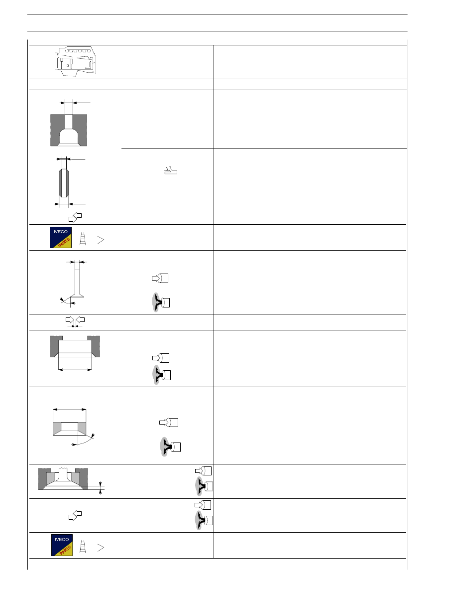
CYLINDER HEAD — TIMING SYSTEM
mm
∅ 1
Valve guide seats on
cylinder head
∅ 1
7.042 to 7.062
2
∅
∅ 3
∅ 2
Valve guides
∅ 3
-
-
Valve guides and seats on head
-
Valve guides
-
∅
α
4
Valves:
∅ 4
α
∅ 4
α
6.970 to 6.999
60
± 0.25°
6.970 to 6.999
45
± 0.25°
Valve stem and guide
0.043 to 0.092
∅ 1
Housing on head for
valve seat:
∅1
∅1
34.837 to 34.863
34.837 to 34.863
α
2
∅
Valve seat outside diameter;
valve seat angle on cylinder
head:
∅ 2
α
∅ 2
α
34.917 to 34.931
60
°
34.917 to 34.931
45
°
X
X
Sinking
X
0.59 to 1.11
0.96 to 1.48
Between valve seat
and head
0.054 to 0.094
0.054 to 0.094
Valve seats
-
SECTION 2 - G-DRIVE APPLICATION
17
G-DRIVE ENGINES
Print P2D32N003GB
Base - February 2006
Type
6 CYLINDERS
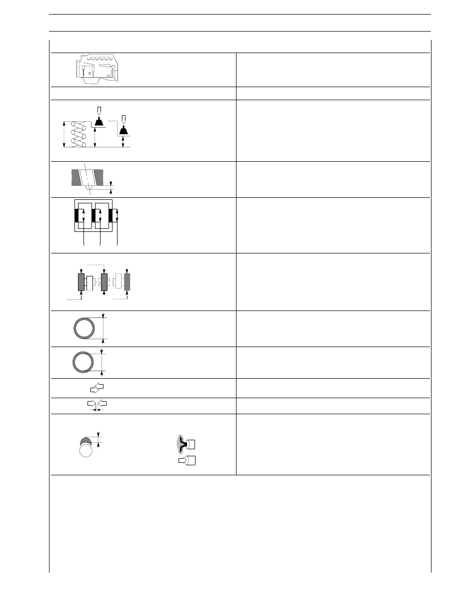
CYLINDER HEAD — TIMING SYSTEM
mm
H
H 1
H 2
Valve spring height:
free spring
H
under a load equal to:
339.8
± 9 N
H1
741
± 39 N
H2
47.75
35.33
25.2
X
Injector protrusion
X
-
∅
∅
∅
1 2 3 4
5
Camshaft bush
housings No. 1
Camshaft housings
No. 2-3-4-5-6-7
59.222 to 59.248
54.089 to 54.139
∅
∅
∅
1
2
3
Camshaft journals:
1
⇒ 7
∅
54.005 to 54.035
∅
Camshaft bush outside
diameter:
∅
-
∅
Bush inside
diameter
∅
54.083 to 54.147
Bushes and housings
on block
-
Bushes and journals
0.038 to 0.162
H
Cam lift:
H
H
6.045
7.582
18
SECTION 2 - G-DRIVE APPLICATION
G-DRIVE ENGINES
Base - February 2006
Print P2D32N00GB
Type
6 CYLINDERS
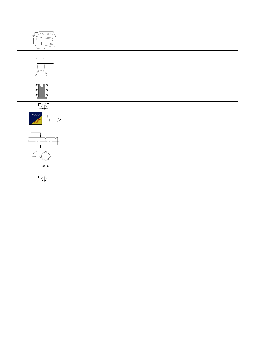
CYLINDER HEAD — TIMING SYSTEM
mm
∅ 1
Tappet cap housing
on block
∅ 1
16.000 to 16.030
∅ 2
3
∅
∅
2
Tappet cap outside
diameter:
∅ 2
∅ 3
15.924 to 15.954
15.960 to 15.975
Between tappets and housings
0.025 to 0.070
Tappets
-
∅ 1
Rocker shaft
∅ 1
21.965 to 21.977
∅ 2
Rockers
∅ 2
22.001 to 22.027
Between rockers and shaft
0.024 to 0.162
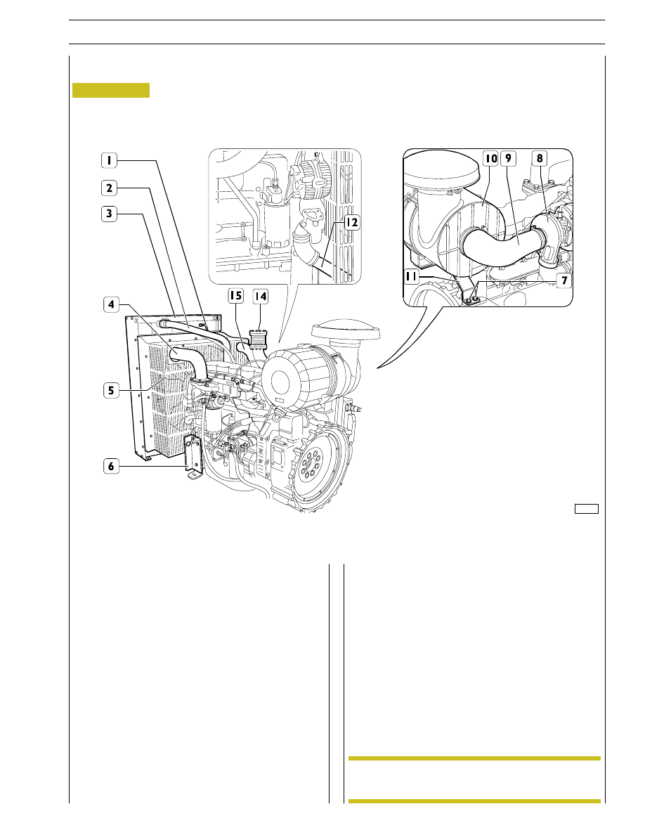
Figure 4
Removal
Remove the fan safety grilles (5) by undoing the relevant
fasteners.
Place a container under the pipe (12) to collect the coolant.
Disconnect and remove the pipe (12) together with the
sleeves by undoing the clamps.
Disconnect the air pipes (4) and (15) from the air exchanger
and from the engine, then remove it from its seat. Disconnect
the exhaust pipe (14) from the system.
Disconnect and remove the coolant pipes (1) and (2).
Block the radiator assembly (3) appropriately, then detach it
from the crankcase by undoing the fasteners (6) on both
sides.
Remove the radiator assembly from its seat, taking care over
any interference with the fan.
108598
Check the state of wear of the rubber couplings.
REMOVING AND REFITTING ENGINE FROM RADIATOR
Disconnect the air hose (9) from air filter (10) to the turbine
(8).
Remove the air cleaner (10) by undoing the fasteners (7) and
remove it from its seat together with the support (11).
Refitting
Proceed by reversing the operations described for removal;
restore the coolant system.
NOTE
SECTION 2 - G-DRIVE APPLICATION
19
G-DRIVE ENGINES
Print P2D32N003GB
Base - February 2006
Нет комментариевНе стесняйтесь поделиться с нами вашим ценным мнением.
Текст