Engines Iveco N45, N67. Manual — part 14
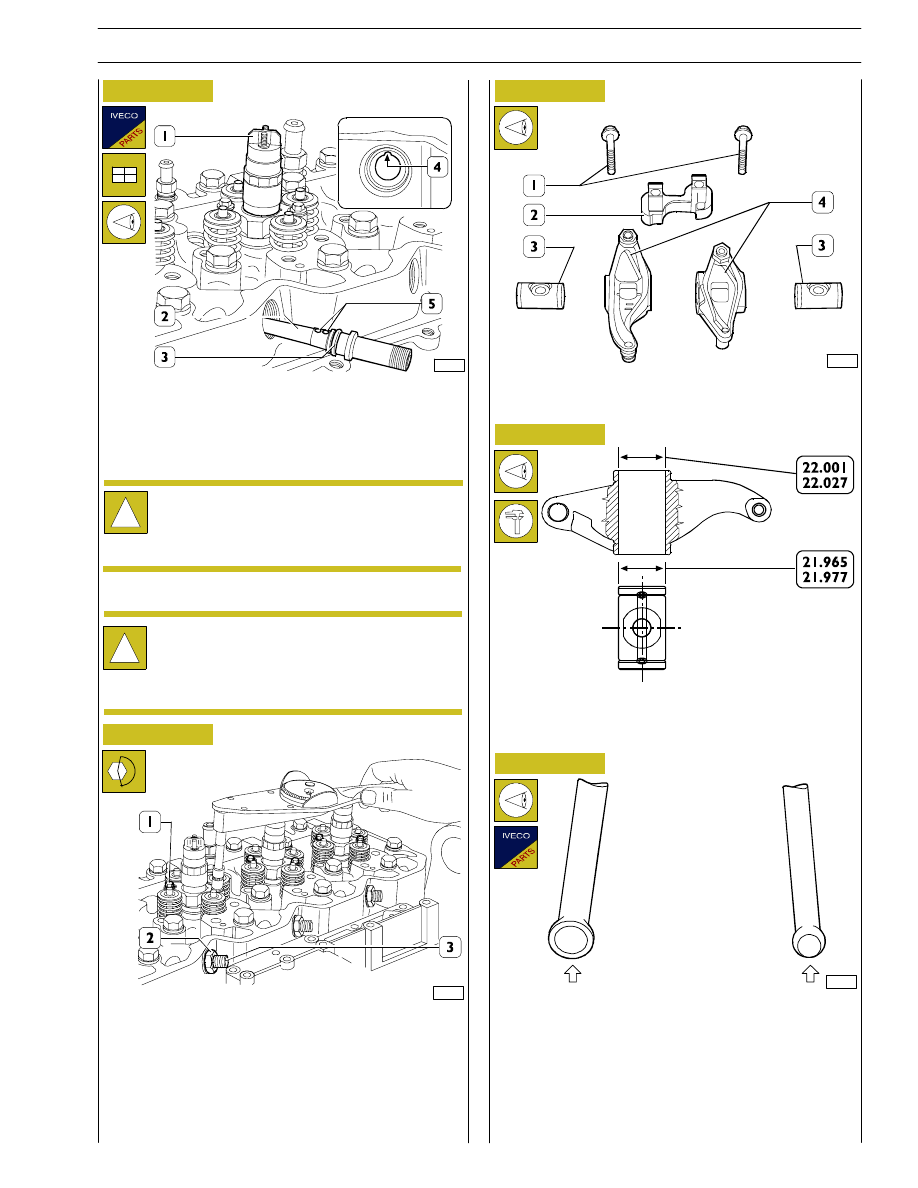
Figure 74
Figure 75
Figure 76
Figure 77
91572
Fit a new sealing ring (3) lubricated with petroleum jelly on
the fuel manifold (2) and fit it into the cylinder head seat so
that the positioning ball (5) is coinciding with the relevant
housing (4).
!
Disassembled fuel manifolds (2) must not be used
again. Replace with new items.
The fuel manifolds (2) for F4HE0684 engines have
2 positioning spheres.
!
During this operation, the injector (1) shall be
moved so that the manifold (2, Figure 72) is properly
inserted into the fuel inlet hole (2, Figure 74).
70342
Use the torque wrench to tighten gradually and alternately
the injector fastening screws (1) to 8.5
± 0.8 Nm torque.
Tighten the fuel manifold (3) fastening nuts (2) to 50 Nm
torque.
Carry out the assembly of the equalisers’ unit , after previous
check of the components.
70343
ROCKER ASSEMBLY COMPONENTS:
1. Screws - 2. Bracket - 3. Shafts - 4. Rockers.
SHAFT-ROCKER MAIN DATA
Check that shaft/rocker coupling surfaces are not showing
excessive wear or damages.
Rocker control rods shall not be distorted; the ball seats in
touch with the rocker adjusting screw and with tappets
(arrows) shall not show seizing or wear; otherwise replace
them. Intake and exhaust valve control rods are identical and
are therefore interchangeable.
32655
Figure 78
Screw the fastening nuts (2, Figure 75) without locking them.
SECTION 3 - DUTY-INDUSTRIAL APPLICATION
25
F4HE NEF ENGINES
Print P2D32N003GB
Base - February 2006

Figure 79
Figure 80
Figure 81
70345
Fit the rods (2).
Position jumpers (1) on valves with marks (
→) facing the
exhaust manifold.
70346
Check that tappet adjusters (1) are loose to prevent their
balking on the rods (2, Figure 79) when refitting the rocker
assembly.
Then refit the rocker assembly consisting of: bracket (5),
rockers (3), shafts (4) and secure them to the cylinder head
by tightening the fastening screws (2) to 36 Nm torque.
70520
Adjust clearance between rockers and valves using setscrew
wrench (1), box wrench (3) and feeler gauge (2).
Clearance shall be as follows:
-
intake valves 0.25
± 0.05 mm
-
exhaust valves 0.50
± 0.05 mm.
!
On TIER 3 engines, due to the additional lobe for the
INTERNAL E.G.R., it is not possible to use the valve
clearance adjustment procedure that requires
adjusting the clearance of all the valves by positioning
the crankshaft 2 times only.
Each cylinder must be checked by taking it to the
T.D.C. (top dead centre) at the end of compression
and adjusting the clearance of both valves on the
cylinder in question.
26
SECTION 3 - DUTY-INDUSTRIAL APPLICATION
F4HE NEF ENGINES
Base - February 2006
Print P2D32N00GB

Figure 82
Figure 83
Figure 84
Figure 85
Apply to the coupling surface of the intake manifold (1)
equipped with heater (2) a sufficient coat of LOCTITE 5999
and provide tightening the screws to the prescribed matching
couple.
Fit the rail (2) and tighten the screws (1) to the specified
torque, connect the ground cable (3) to the intake manifold
(4) and tighten the fastening nut to the specified torque.
Connect new fuel pipes (1) to rail (3) and injector manifolds
(2).
!
Pipe (7) connections shall be tightened to 20 Nm
torque, using the proper wrench (5) and the torque
wrench 99389833 (4).
Connections (6) shall be tightened by holding the
flow limiting valve hexagon (1) with the proper
wrench.
Connect the fuel pipe (3) to the rail (2) following the
procedure shown in the following figure.
70126
Press the clamp (1) in arrow direction (Figure B) and connect
the pipe to the rail, reset the clamp to the initial locking
position “A”.
!
Check proper fuel pipe connection.
Figure 86
108547
108567
108568
108569
SECTION 3 - DUTY-INDUSTRIAL APPLICATION
27
F4HE NEF ENGINES
Print P2D32N003GB
Base - February 2006

70352
Figure 87
Figure 88
Figure 89
Figure 90
Check electrical cable (5) conditions, replace if damaged by
cutting the support (2) clamps and removing the screws (4)
that secure it to connections (3).
Fit a new gasket (1) on the support (2).
Fit the wiring support (2) and tighten the screws (1) to the
specified torque.
Fit a new gasket (2) on the tappet cover (1).
Place the tappet cover on, install the bolts in the correct
position and tighten.
70355
Reconnect the exhaust manifold (2) with new gaskets. Tighten
the fastening screws (1) to the specified torque.
Sling the turbocharger (1) and place it over the manifold after
having first inserted a new gasket.
Connect the oil pipeline (3) to the support of the heat
exchanger /oil filter. Fix the pipe (3) to the pipe fitting on the
turbocharger.
!
Before any assembly operation always verify that the
hole and screw threads have no evidence of wear or
dirt.
Connect the electrical cables (1) to the injectors (3) and use
the torque wrench 99389834 (4) to tighten the fastening
nuts (2) to the specified torque.
Figure 91
108570
108571
108572
28
SECTION 3 - DUTY-INDUSTRIAL APPLICATION
F4HE NEF ENGINES
Base - February 2006
Print P2D32N00GB
Нет комментариевНе стесняйтесь поделиться с нами вашим ценным мнением.
Текст