Engines Iveco N45, N67. Manual — part 15
74170
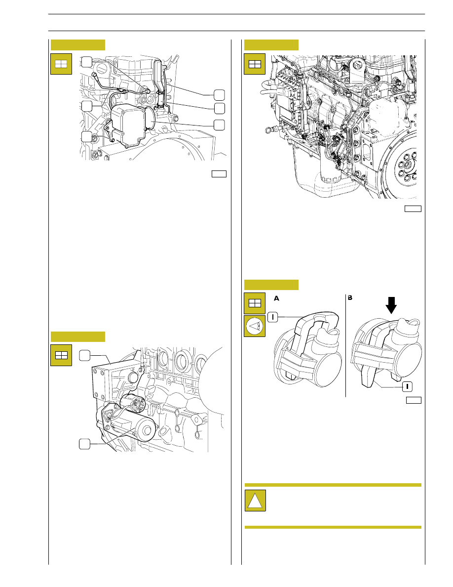
Figure 92
Insert the blow-by filter (4) tightening the screws.
Connect the pipeline (6) and fix the oil vapour recover pipe
through the clamp (5); lock up the nut fixing it to the upper
edge.
Connect the pipeline (2) to the pressure- limiter (1).
1
2
3
4
5
6
Figure 93
1
2
Assemble the starter (2) to the internal part of the flywheel
cover.
Assemble the oil feeding pipe using a new O-ring. Fix with
three M12x25 screws.
Assemble the bracket and the support (1) of the fuel filter (6).
Proceed connecting in sequence the pipelines (9,3,4 and 5)
of the support (1) to the high pressure pump (8).
Connect the pipeline (7) from the high pressure pump to the
engine control module heat exchanger.
Connect the pipeline (10) from the high pressure pump to
the rail diffuser.
Figure 94
70126
All the fuel pipelines are fixed using the clamps shown in the
picture.
For the connection of the pipes, press the clamp (I) following
the arrow’s direction (Figure B) and connect the pipe to the
clamp on the high pressure pump or on the support of the
fuel filter.
Reset the clamp in the initial locking ”A” position.
!
In case the pipes are re-employed, they must keep
the sealing tops at the edges.
Make sure that the fuel pipeline is correctly
connected.
Reconnect the engine harness to all the sensors, the engine
control module and the rail diffuser (see Figure 6)
Figure 95
108541
Completion of the engine
Properly handle the engine holding it by a lifter, remove it
from the rotating shaft, remove the brackets 99341009 and
place it on proper suitable support to carry out the
completion.
Proceed assembling the oil filter.
SECTION 3 - DUTY-INDUSTRIAL APPLICATION
29
F4HE NEF ENGINES
Print P2D32N003GB
Base - February 2006
- that there are no water leaks from the connecting
sleeves of engine cooling circuit pipes and cab internal
heating pipes, tighten the clamping collars if required;
- check carefully the connection between the low
pressure fuel pipes and the relevant connectors;
- that there are no oil leaks between the cover and the
cylinder head, between oil sump and engine block,
between heat exchanger oil filter and the relevant
housings and between the different pipes in the
lubricating circuit;
- that there are no fuel leaks from the fuel pipes;
- that there are no air leaks from pneumatic pipes (if
fitted);
- check also proper operation of the warning lights set on
the
instrument
panel
and
of
the
equipment
disconnected when engine was removed.
- Carefully check and bleed the engine cooling equipment
by repeated draining operations.
Checks and inspections
Start the engine and leave it running just above the
idling speed, wait until the coolant reaches the
temperature necessary to open the thermostat and
then check:
!
The following checking inspections must be carried
out after the engine assembly on the vehicle .
30
SECTION 3 - DUTY-INDUSTRIAL APPLICATION
F4HE NEF ENGINES
Base - February 2006
Print P2D32N00GB
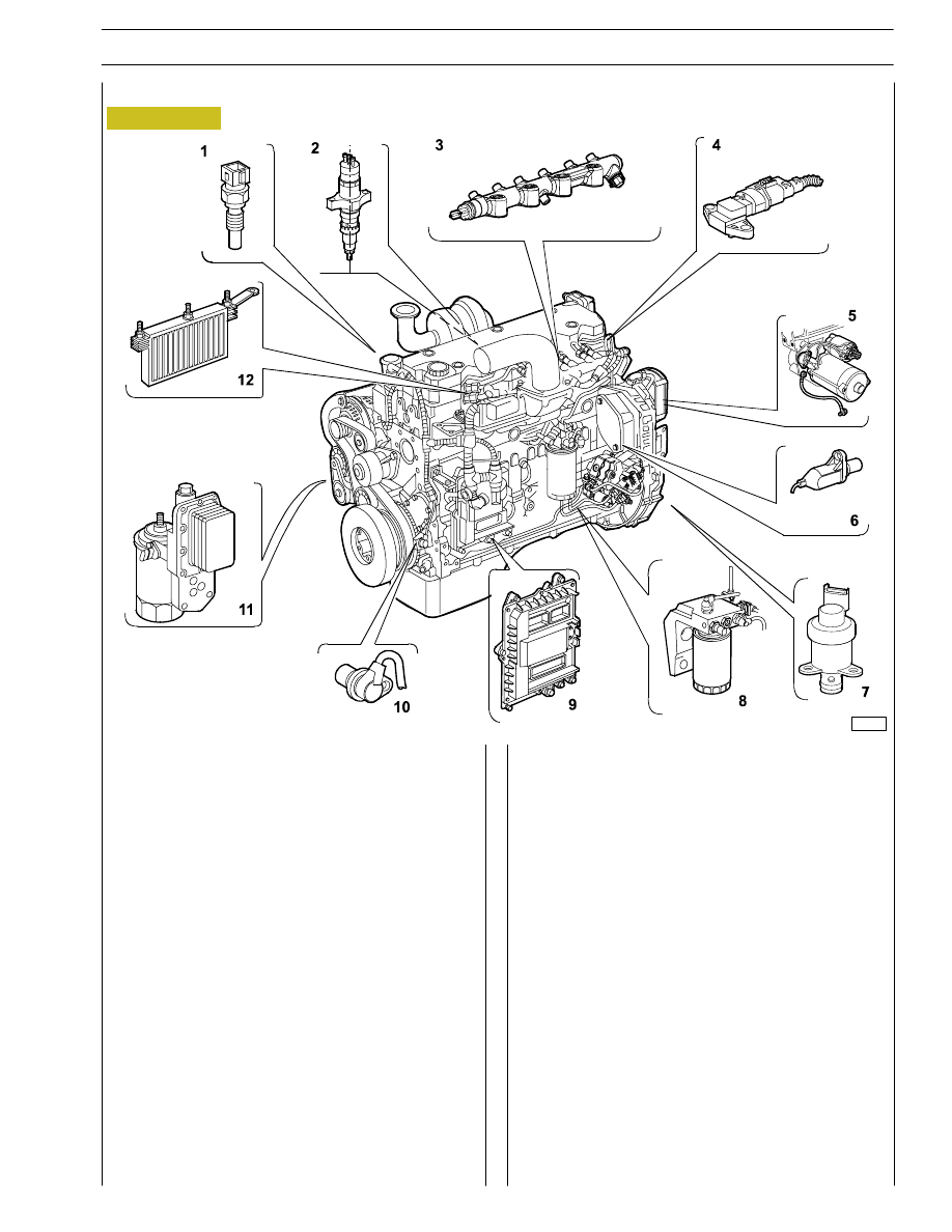
Figure 96
The NEF F4HE engines are fully driven by the electronic
engine control module, which is assembled directly to the
engine by means of a heat exchanger enabling its cooling,
utilising rubber buffers to reduce vibration originated by the
engine.
Through the engine control module it is possible to verify the
correct working of the engine. (See part three of the hereby
user’s guide specifically dedicated to diagnostic).
The electrical and electronic components of the engine are
listed here following:
1. Coolant temperature sensor.
2. Electro-injector.
3. RAIL pressure sensor.
4. Air temperature/pressure sensor.
6. Timing sensor.
7. Solenoid valve for pressure regulator.
8. Fuel temperature sensor.
9. EDC electronic control unit.
10. Crankshaft sensor.
11. Engine oil pressure/temperature sensor.
12. Heating element for pre-post heating.
LOCATION OF THE MAIN ELECTRICAL COMPONENTS
108641
SECTION 3 - DUTY-INDUSTRIAL APPLICATION
33
F4HE NEF ENGINES
Print P2D32N003GB
Base - February 2006
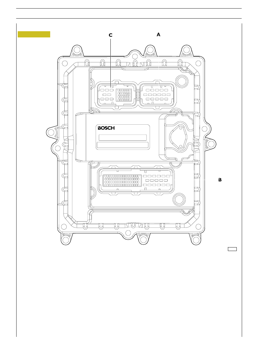
Figure 97
A - Connector to injectors; B - Connector to chassis (Provide reference of the vehicle to which the engine is assembled);
C - Connector to sensors.
01525t
EDC7 ECU
34
SECTION 3 - DUTY-INDUSTRIAL APPLICATION
F4HE NEF ENGINES
Base - February 2006
Print P2D32N00GB
Нет комментариевНе стесняйтесь поделиться с нами вашим ценным мнением.
Текст