Engines Iveco N45, N67. Manual — part 12
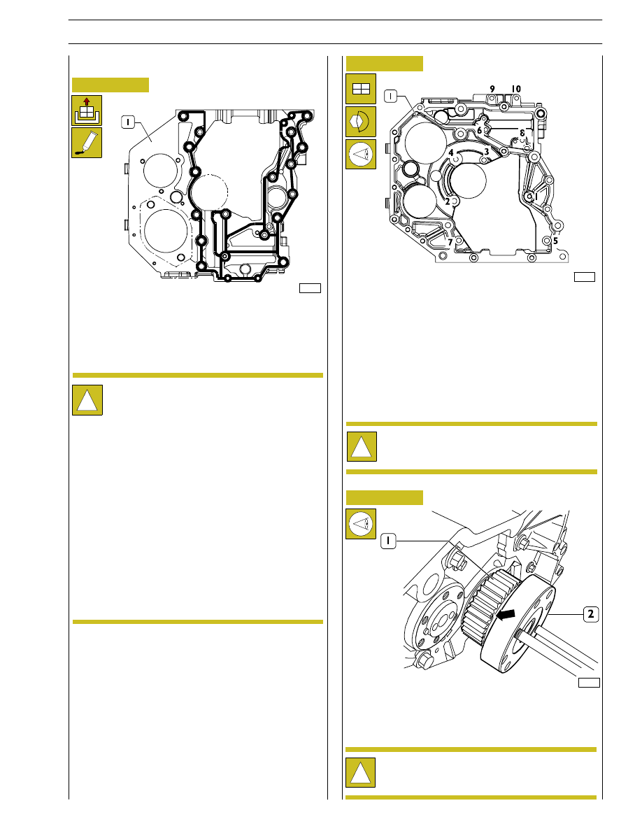
DIAGRAM FOR TIGHTENING THE REAR TIMING
GEAR CASE FASTENING SCREWS
Refit the case (1) to the engine block.
Screw the fastening screws in the same position found at
removal and tighten them to the following torque values in
the sequence shown in the figure:
Screws M12
65 to 89 Nm
Screws M8
20 to 28 Nm
Screws M10
42 to 52 Nm
Figure 36
Assembly of application components
LOCTITE 5205 SEALANT APPLICATION AREAS
Clean accurately the timing gear case (1) and the engine
block.
70209
!
Perfect seal is only obtained by cleaning accurately
the surface to seal.
Smear the case with LOCTITE 5205 to obtain a bead
of few mm diameter.
It shall be uniform (no clots), without air bubbles, thin
areas or discontinuities.
Any imperfection shall be corrected as soon as
possible.
Avoid to use excess material to seal the joint.
Excessive sealant could come out from joint sides
and cause lubricant passage clogging.
After applying the sealant, the joint shall be
assembled immediately (10 — 20 minutes).
70210
Figure 37
Figure 38
70211
Use a felt pen to mark the driving gear (1) tooth fitted on the
output shaft (2) having the mark (
→) for timing on the side
surface.
!
Fasten screwing of the two pins to facilitate the
operation of engine driving shaft rotation.
!
Before any assembly operation always verify that the
hole and screw threads have no evidence of wear or
dirt.
SECTION 3 - DUTY-INDUSTRIAL APPLICATION
17
F4HE NEF ENGINES
Print P2D32N003GB
Base - February 2006

Figure 39
Rotate the output shaft (4) and the camshaft (2) so that when
fitting the driven gear (1) on the camshaft the marks on the
gears (1 and 3) are coinciding.
Figure 40
70213
Tighten the screws (1) fastening gear (2) to camshaft (3) to
the specified torque.
Figure 41
70214
LOCTITE 5205 SEALANT APPLICATION AREAS
!
Perfect seal is only obtained by cleaning accurately
the surface to seal.
Smear the case with LOCTITE 5205 to obtain a bead
of few mm diameter.
It shall be uniform (no clots), without air bubbles, thin
areas or discontinuities.
Any imperfection shall be corrected as soon as
possible.
Avoid to use excess material to seal the joint.
Excessive sealant could come out from joint sides
and cause lubricant passage clogging.
After applying the sealant, the joint shall be
assembled immediately (10 — 20 minutes).
Figure 42
70215
SEQUENCE FOR TIGHTENING THE FLYWHEEL
HOUSING FASTENING SCREWS
Refit the housing (1) to the engine block and screw the
fastening screws in the same position found at removal and
tighten them to the following torque values in the sequence
shown in the figure:
Screws M12
75 to 95 Nm
Screws M10
44 to 53 Nm
Not available
On engines
F4AE0684H-E
F4HE0684E-F-J
!
Before any assembly operation always verify that the
hole and screw threads have no evidence of wear or
dirt.
108577
18
SECTION 3 - DUTY-INDUSTRIAL APPLICATION
F4HE NEF ENGINES
Base - February 2006
Print P2D32N00GB

Figure 43
70217
!
Where the engine is coupled to a mechanical clutch,
verify that the flywheel nominal thickness of 49,6
±
0,13 mm.
Check ring gear teeth (2), if breakage or excessive wear is
found remove the ring gear from the engine flywheel (1,
Figure 43) using a suitable hammer and fit the new one,
previously heated to 150
°C for 15 to 20 minutes. Chamfering
on ring gear inside diameter shall be facing the engine
flywheel.
Figure 44
Figure 45
Apply tool 99360339 (2) to the flywheel housing to stop
engine flywheel (3) rotation. Tighten the screws (1) fastening
the engine flywheel (3) to the output shaft.
Figure 46
70219
α
!
Tightening to angle is performed using tool
99395216.
Before any assembly operation always verify that the
hole and screw threads have no evidence of wear or
dirt.
Apply tool 99346252 part (6) to the rear output shaft tang
(5), secure it by screws (4) and fit the new sealing ring (3).
Position part (1) on part (5), screw nut (2) until completing
sealing ring (3) fitting into flywheel housing (7).
Screw two pins (2) having suitable length into shaft holes (3)
and remove the engine flywheel (1) using proper sling and
hoister.
70152
Figure 47
0901t
Tighten engine flywheel (2) fastening screws (1) in two
stages:
- 1
st
stage, tightening to 30
± 4 Nm torque with
dynamometric wrench;
- 2
nd
stage, tightening to 60
± 5° angle.
SECTION 3 - DUTY-INDUSTRIAL APPLICATION
19
F4HE NEF ENGINES
Print P2D32N003GB
Base - February 2006

Figure 48
70220
Fit the oil pump (1).
Tighten the fastening screws (2) to the specified torque.
Figure 49
70221
Apply a new sealing ring (2) to the water pump (1).
Figure 50
Fit the water pump (1).
Tighten the screws (2) to the specified torque.
Figure 51
70223
Remove the sealing ring (2) from the front cover (1), clean
accurately the coupling surfaces and smear them with
LOCTITE 5205.
Clean accurately the front cover (2) surface and refit it.
Tighten the screws (1) to the specified torque.
Figure 52
Apply tool 99346252 part (4) to the front output shaft tang
(6), secure it by screws (5) and fit the new sealing ring (7).
Position part (2) on part (4), screw nut (3) until completing
sealing ring (7) fitting into front cover (1).
00902t
Figure 53
70222
70224
20
SECTION 3 - DUTY-INDUSTRIAL APPLICATION
F4HE NEF ENGINES
Base - February 2006
Print P2D32N00GB
Нет комментариевНе стесняйтесь поделиться с нами вашим ценным мнением.
Текст