Engines Iveco N45, N67. Manual — part 31
50676
70334
770321
Figure 86
Figure 87
Figure 88
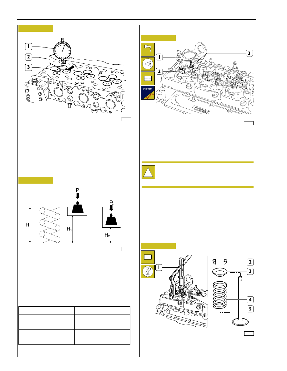
MAIN DATA TO CHECK INTAKE AND EXHAUST
VALVE SPRINGS
Before refitting use tool 99305047 to check spring flexibility.
Compare load and elastic deformation data with those of the
new springs shown in the following table.
FITTING CYLINDER HEAD
Lubricate the valve stems (1) and fit them into the relevant
valve guides according to the position marked at removal.
Fit the sealing rings (2 and 3) on the valve guide.
Position on the cylinder head: the spring (4), the upper cap
(3); use tool 99360268 (1) to compress the spring (4) and
lock the parts to the valve (5) by the cotters (2).
!
Sealing rings (2) for intake valves are yellow and
sealing rings (3) for exhaust valves are green.
VALVE SPRINGS
70333
Figure 89
After regrinding, check that valve (3) sinking value is the
specified one by using the base 99370415 (2) and the dial
gauge 99395603 (1).
38
SECTION 4 - OVERHAUL AND TECHNICAL SPECIFICATIONS
F4HE NEF ENGINES
Base - February 2006
Print P2D32N00GB
Height
Under a load of
mm
kg
H
47.75
Free
H
1
35.33
P
339.8
± 19 N
H
2
25.2
P1
741
± 39 N
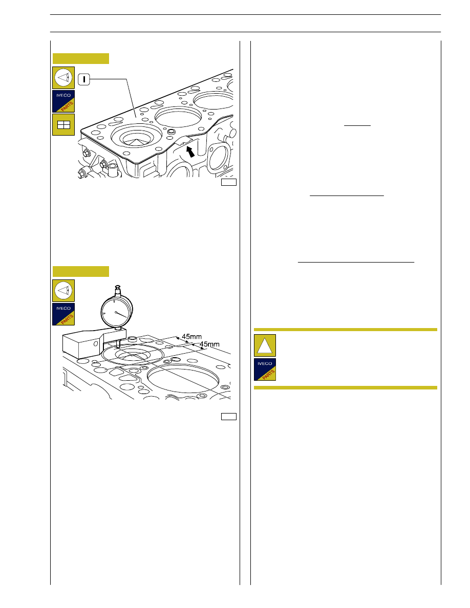
Check cleanness of cylinder head and engine block coupling
surface.
Take care not to foul the cylinder head gasket.
Set the cylinder head gasket (1) with the marking “TOP” (1)
facing the head.
The arrow shows the point where the gasket thickness is
given.
70335
Figure 90
Refitting the cylinder head
!
Before re-utilising the fixing screws for the cylinder
head, verify there is no evidence of wear or
deformation and in that case replace them.
88775
Figure 91
There are two types of head seals for F4AE04.., F4AE06.. and
F4HE06.. engines, for the thickness (1.25 mm Type A and
1.15 mm Type B) take the following measures:
- for each piston detect, as indicated on NO TAG, at a
distance of 45 mm from the centre of the piston
overhandings S1 and S2 in relation to the engine base
upper plane then calculate the average:
For 4 cylinder versions:
Repeat the operation for pistons 2, 3 and 4 and calculate the
average value.
For 6 cylinder versions:
Repeat the operation for pistons 2, 3, 4, 5 and 6 and calculate
the average value.
If S is > 0,40 mm use seal type A.
If S is < 0,40 mm use seal type B.
S
=
S
cil1
+ S
cil2
+ S
cil3
+ S
cil4
+ S
cil5
+ S
cil6
6
S
cil1
= S1 + S2
2
S
=
S
cil1
+ S
cil2
+ S
cil3
+ S
cil4
4
SECTION 4 - OVERHAUL AND TECHNICAL SPECIFICATIONS
39
F4HE NEF ENGINES
Print P2D32N003GB
Base - February 2006

40
SECTION 4 - OVERHAUL AND TECHNICAL SPECIFICATIONS
F4HE NEF ENGINES
Base - February 2006
Print P2D32N00GB
TIGHTENING TORQUE
COMPONENT
TORQUE
COMPONENT
Nm
kgm
Studs M6 for camshaft sensors
8
± 2
0.8
± 0.2
Studs M8 for feed pump
12
± 2
1.2
± 0.2
Screw M12 for fastening rear gear case
Screw M10 for fastening rear gear case
Screw M8 for fastening rear gear case
77
± 12
47
± 5
24
± 4
7.7
± 1.2
4.7
± 0.5
2.4
± 0.4
Nut M6 for fastening camshaft sensor
10
± 2
1
± 0.2
Screw M8 for fastening oil pump
1
st
stage
2
nd
stage
8
± 1
24
± 4
0.8
± 0.1
2.4
± 0.4
Screw M8 for fastening front cover
24
± 4
2.4
± 0.4
Screw M8 for fastening camshaft longitudinal retaining plate
24
± 4
2.4
± 0.4
Screw M8 for fastening camshaft gear
36
± 4
3.6
± 0.4
Screw M10 for fastening crankcase plate
43
± 5
4.3
± 0.4
Nut M18 for fastening high pressure pump gear
105
± 5
10.5
± 0.5
Nuts M8 for fastening fuel pump
24
± 4
2.4
± 0.4
½ inch plug on cylinder head
¼ inch plug on cylinder head
¾ inch plug on cylinder head
24
± 4
36
± 5
12
± 2
2.4
± 0.4
3.6
± 0.5
1.2
± 0.2
Screw M6 for fastening injectors
1
st
stage
d
8.5
± 0.35
0.85
± 0.035
Screw M6 for fastening injectors
1 stage
2
nd
stage
75º
± 5º
Nut fastening for injector feed connector
50
± 5
5
± 0.5
Nut M6 for flame start grille on intake manifold
8
± 2
0.8
± 0.2
Screw M8 for fastening intake manifold
24
± 4
2.4
± 0.4
Screw M12 for fastening rear brackets for engine lifting
77
± 12
7.7
± 1.2
Screws M8 for fastening Common Rail
24
± 4
2.4
± 0.4
Connectors M14 for high pressure fuel pipes
20
± 2
2
± 0.2
Screw M12 (12 x 1.75 x 130) for fastening cylinder head
1
st
stage
}
35
± 5
3.5
± 0.5
Screw M12 (12 x 1.75 x 150) for fastening cylinder head
1
st
stage
}
55
± 5
5.5
± 0.5
2
nd
stage
90º
± 5º
3
rd
stage
90º
± 5º
Screw for fastening rocker bracket
36
± 5
3.6
± 0.5
Valve clearance adjusting nuts
24
± 4
2.4
± 0.4
Nuts M14 for fastening fuel pipes from high pressure pump to Common Rail
20
± 2
2
± 0.2
Screw M8 for fastening high pressure pipe connector
24
± 4
2.4
± 0.4
Screw M6 for fastening wiring bulkhead
10
± 2
1
± 0.2
Screw M8 for fastening electric wiring support for injector feed
24
± 4
2.4
± 0.4
Nuts for fastening wiring on each injector
1.5
± 0.25
0.15
± 0.025
Screw M12 for fastening fuel filter bracket
77
± 8
7.7
± 0.8
Screw M8 for fastening fuel filter holder
24
± 4
2.4
± 0.4
Fuel filter
contact +
¾ turn
Screw M22 for fastening oil pressure relief valve on oil filter support
80
± 8
8
± 0.8
Screw M8 for radiator seal and oil filter support
24
± 4
2.4
± 0.4
Oil filter
contact +
¾ turn
11/8 inch connection on filter support for turbine lubrication
24
± 4
2.4
± 0.4
Nut M12 for fastening turbine lubrication pipe
10
± 2
1
± 0.2
Screw M10 for fastening engine coolant inlet connection
43
± 6
4.3
± 0.6
90
° elbow fastening (if required) to engine coolant inlet connection
24
± 4
2.4
± 0.4
Pipe on cylinder head for compressor cooling
22
± 2
2.2
± 0.2

SECTION 4 - OVERHAUL AND TECHNICAL SPECIFICATIONS
41
F4HE NEF ENGINES
Print P2D32N003GB
Base - February 2006
COMPONENT
TORQUE
COMPONENT
Nm
kgm
Screw M6 for fastening engine coolant drain connector
10
± 2
1
± 0.2
Pin fastening on engine block for exhaust manifold
10
± 2
1
± 0.2
Screw M10 for fastening exhaust manifold on cylinder head
53
± 5
5.3
± 0.5
Screw M12 for fastening damper adapter
1
st
stage
50
± 5
5
± 0.5
Screw M12 for fastening damper adapter
1 stage
and damper on output shaft
2
nd
stage
90º
Screw M10 for fastening pulley on output shaft
68
± 7
6.8
± 0.7
Screw M8 for fastening water pump
24
± 4
2.4
± 0.4
Screw M10 for fastening auxiliary component control belt tensioners
43
± 6
4.3
± 0.6
Screw M10 for fastening fixed pulleys for auxiliary component control belt
43
± 6
4.3
± 0.6
Screw M10 for fastening flywheel housing
Screw M12 for fastening flywheel housing
85
± 10
49
± 5
8.5
± 1
4.9
± 0.5
Screw M6 for fastening heat exchanger for control unit
Screw M8 for fastening heat exchanger for control unit
10
± 2
24
± 4
1
± 0.2
2.4
± 0.4
Connection M12 for fuel inlet-outlet on heat exchanger
12
± 2
1.2
± 0.2
Nut M8 for fastening valve cover
24
± 4
2.4
± 0.4
Screw M6 for fastening camshaft sensor
8
± 2
0.8
± 0.2
Screw M6 for fastening output shaft sensor
8
± 2
0.8
± 0.2
Screw M14 for fastening coolant temperature sensor
20
± 3
2
± 0.3
Screw M5 for fastening oil pressure/temperature sensor
6
± 1
0.6
± 0.1
Screw for fastening fuel pressure sensor
35
± 5
3.5
± 0.5
Screw M14 for fastening fuel temperature sensor
20
± 3
2
± 0.3
Screw for fastening air temperature/pressure sensor on intake manifold
6
± 1
0.6
± 0.1
Screw M12 for fastening engine oil level sensor
12
± 2
1.2
± 0.2
{
pins
M8
t
M8
6-cyl.
7
± 1
43
± 6
0.7
± 0.1
4 3
± 0 6
Turbine fixing to exhaust manifold
{
nuts
M8
6-cyl.
{
pins
M8
43
± 6
7
± 1
4.3
± 0.6
0 7
± 0 1
u b e
g to e
aust
a
o d
4-cyl.
{
pins
M8
nuts
M8
7
± 1
24
± 4
0.7
± 0.1
2.4
± 0.4
Adapter M12 on turbine for lubricant oil pipes (inlet)
35
± 5
3.5
± 0.5
Pipe fixing on adapter M10 for turbine lubrication
35
± 5
3.5
± 0.5
Oil pipe fixing on adapter M10 for turbine lubrication to block
43
± 6
4.3
± 0.6
Oil drain pipe fixing M8 on turbine
24
± 4
2.4
± 0.4
Connector fixing M6 for oil return from cylinder head to flywheel housing
10
± 2
1
± 0.2
Screw M12 for fastening engine flywheel
1
st
stage
d
30
± 4
3
± 0.4
Screw M12 for fastening engine flywheel
1 stage
2
nd
stage
60º
± 5º
Screw M8 for fastening front bracket for engine lifting
24
± 4
2.4
± 0.4
Screw for fastening engine oil sump
24
± 4
2.4
± 0.4
Screw M8 for fastening cylinder barrel lubricating nozzles
15
± 3
1.5
± 0.3
Screw M12 for fastening output shaft caps
1
st
stage
2
nd
stage
d
50
± 6
80
± 6
5
± 0.6
8
± 0.6
2
stage
3
rd
stage
90º
± 5º
Screw M8 for fastening camshaft longitudinal retaining plate
24
± 4
2.4
± 0.4
Screw M8 for fastening camshaft gear
36
± 4
3.6
± 0.4
Screw M11 for fastening connecting rod caps
1
st
stage
d
60
± 5
6
± 0.5
Screw M11 for fastening connecting rod caps
1 stage
2
nd
stage
60º
± 5º
Alternator
M10 Screw, Bracket fixing on water feed pipefitting
43
± 6
4.3
± 0.6
M10 Screw, alternator locking
43
± 6
4.3
± 0.6
Starter
Starter fixing screw
43
± 6
4.3
± 0.6
Нет комментариевНе стесняйтесь поделиться с нами вашим ценным мнением.
Текст