Engines Iveco N45, N67. Manual — part 29
70203
70204
70205
70206
Figure 63
Figure 64
Figure 65
Figure 66
Figure 67
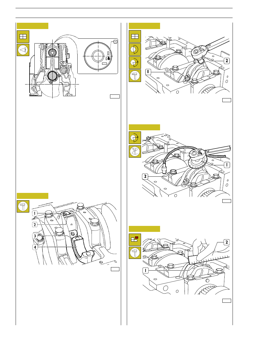
DIAGRAM FOR CONNECTING ROD-PISTON
ASSEMBLY FITTING INTO BARREL
- Split ring openings shall be displaced with each other by
120
°;
- connecting rod-piston assemblies shall have the same
weight;
- the arrow marked on the piston crown shall be facing the
front side of the engine block or the slot obtained on the
piston skirt shall be corresponding to the oil nozzle
position.
Finding crankpin clearance
To measure the clearance proceed as follows:
- clean the parts accurately and remove any trace of oil;
- set a piece of calibrated wire (2) on the output shaft pins
(1);
- fit the connecting rod caps (3) with the relevant half
bearings (4).
- Lubricate the screws (1) with engine oil and then tighten
them to the specified torque using the torque wrench
(2).
- Apply tool 99395216 (1) to the socket wrench and
tighten screws (2) of 60
°.
- Remove the cap and find the existing clearance by
comparing the calibrated wire width (1) with the scale
on the wire envelope (2).
α
α
108596
30
SECTION 4 - OVERHAUL AND TECHNICAL SPECIFICATIONS
F4HE NEF ENGINES
Base - February 2006
Print P2D32N00GB
70207
70208
Figure 68
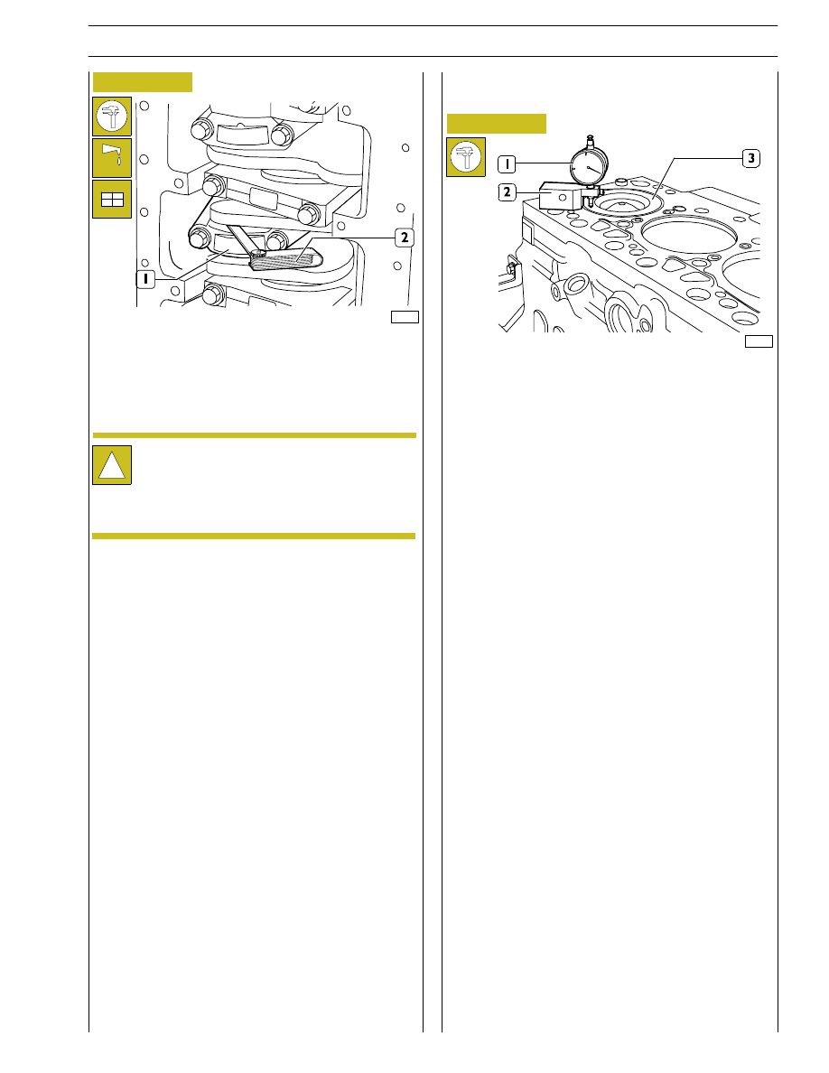
If a different clearance value is found, replace the half bearings
and repeat the check.
Once the specified clearance has been obtained, lubricate
the main half bearings and fit them by tightening the
connecting rod cap fastening screws to the specified torque.
Once connecting rod-piston assemblies refitting is over, use
dial gauge 39395603 (1) fitted with base 99370415 (2) to
check piston (3) protrusion at T.D.C. with respect to the top
of the engine block.
Protrusion shall be 0.28 to 0.52 mm.
!
Before the final fitting of the connecting rod cap
fastening
screws,
check
that
their
diameter
measured at the centre of the thread length is not
< 0.1 mm than the diameter measured at approx. 10
mm from screw end.
Check manually that the connecting rods (1) are sliding
axially on the output shaft pins and that their end float,
measured with feeler gauge (2) is 0.10 to 0.33 mm.
Checking piston protrusion
Figure 69
SECTION 4 - OVERHAUL AND TECHNICAL SPECIFICATIONS
31
F4HE NEF ENGINES
Print P2D32N003GB
Base - February 2006

70319
Figure 70
Intake (1) and exhaust (2) valves have heads with the same
diameter.
The central notch (
→) of the exhaust valve (2) head
distinguishes it from the intake valve.
!
Should cylinder head valves be not replaced, number
them before removing in order to refit them in the
same position.
A = intake side — S = exhaust side
CYLINDER HEAD
Removing the valves
Valve removal shall be performed using tool 99360268 (1)
and pressing the cap (3) so that when compressing the
springs (4) the cotters (2) can be removed. Then remove the
cap (3) and the springs (4).
Repeat this operation for all the valves.
Overturn the cylinder head and withdraw the valves (5).
70321
70322
Figure 71
Figure 72
Remove sealing rings (1 and 2) from the valve guide.
!
Sealing rings (1) for intake valves are yellow.
Sealing rings (2) for exhaust valves are green.
32
SECTION 4 - OVERHAUL AND TECHNICAL SPECIFICATIONS
F4HE NEF ENGINES
Base - February 2006
Print P2D32N00GB
70323
Figure 73
Figure 74
This check shall be performed using the proper tools.
Use a pump to fill with water heated to approx. 90
°C and 2
to 3 bar pressure.
Replace the core plugs (1) if leaks are found, use the proper
punch for their removal/refitting.
Replace the cylinder head if leaks are found.
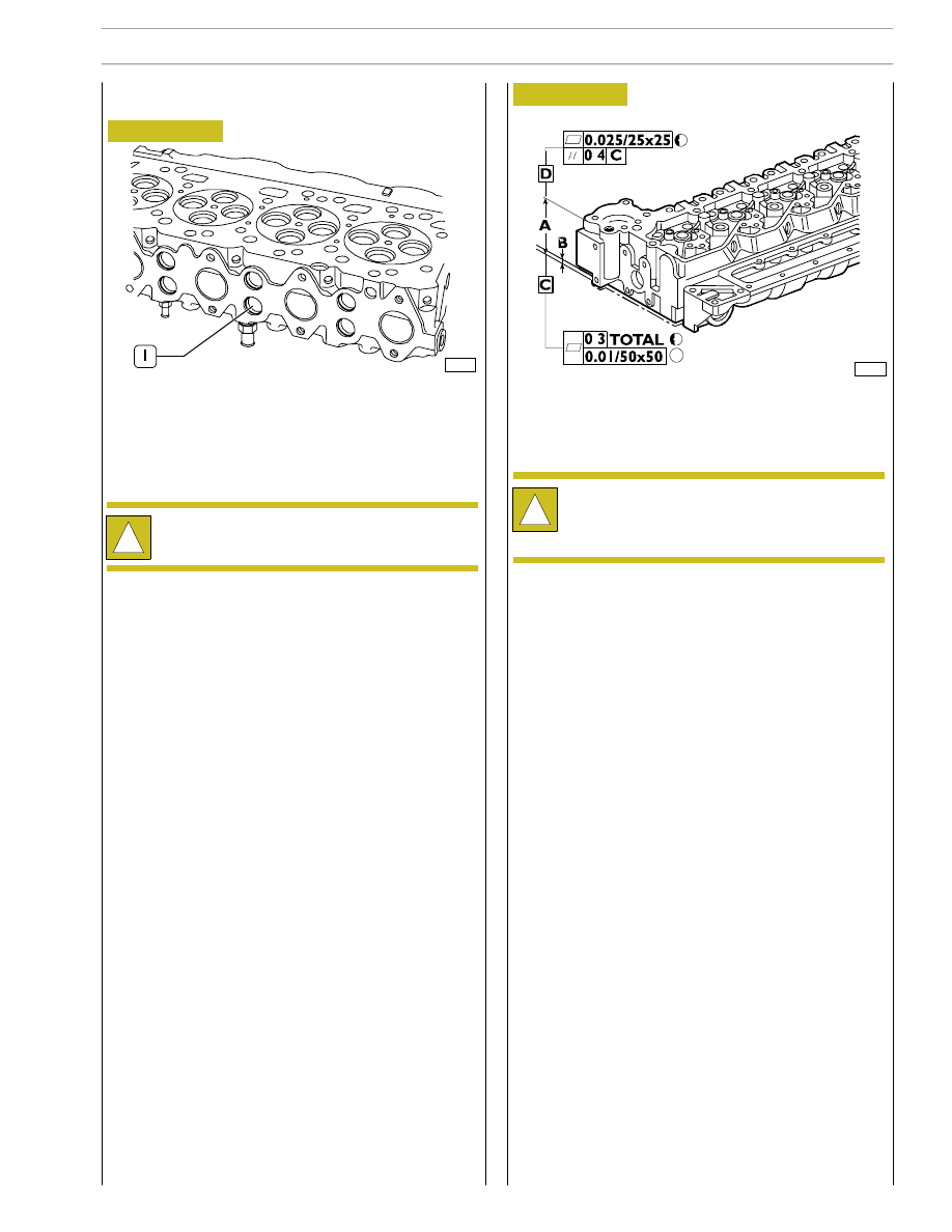
Distortion found along the whole cylinder head shall not
exceed 0.20 mm.
If higher values are found grind the cylinder head according
to values and indications shown in the following figure.
Checking cylinder head wet seal
!
Before refitting, smear the plug surfaces with
water-repellent sealant.
Checking cylinder head supporting surface
70325
The rated thickness A for the cylinder head is 105
± 0.25 mm,
max. metal removal shall not exceed thickness B by 1 mm.
!
After grinding, check valve sinking. Regrind the valve
seats, if required, to obtain the specified value.
SECTION 4 - OVERHAUL AND TECHNICAL SPECIFICATIONS
33
F4HE NEF ENGINES
Print P2D32N003GB
Base - February 2006
Нет комментариевНе стесняйтесь поделиться с нами вашим ценным мнением.
Текст